

Vladislav
-
Posts
8,135 -
Joined
-
Last visited
-
Days Won
79
Content Type
Profiles
Forums
Gallery
Events
Blogs
BMT Wiki
Collections
Store
Everything posted by Vladislav
-
 The job turns out really nice! Hope to see more photos of progress soon. Good luck on the project! Vlad.
 -
His nick name on here is Mack daddy if I'm not wrong. Hope the N-model will be saved one way or another.
-
It has attractive look though. Air start?
-
Yes, same question.
-
Keep the track Gentlemen! Unfortunately our world is not friendly all over. Thanks for the work!
-
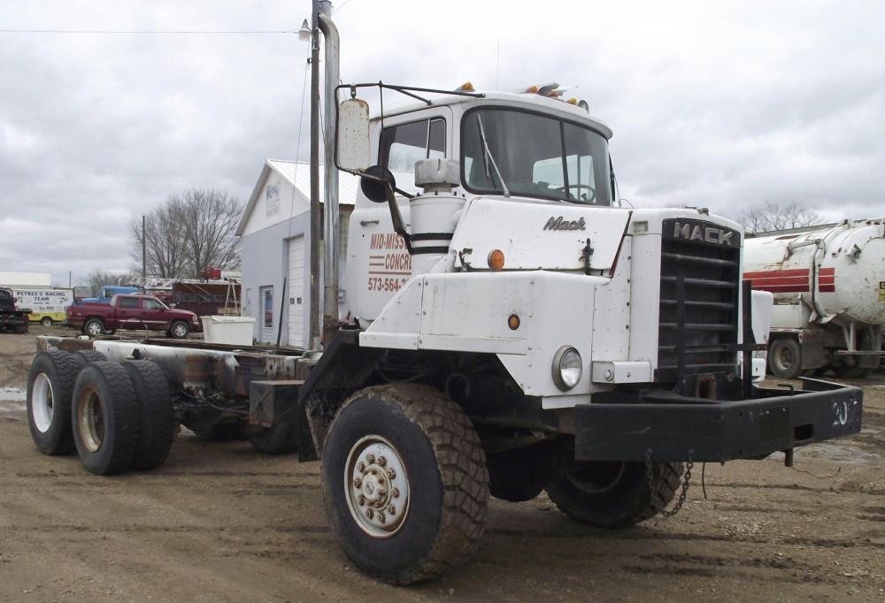
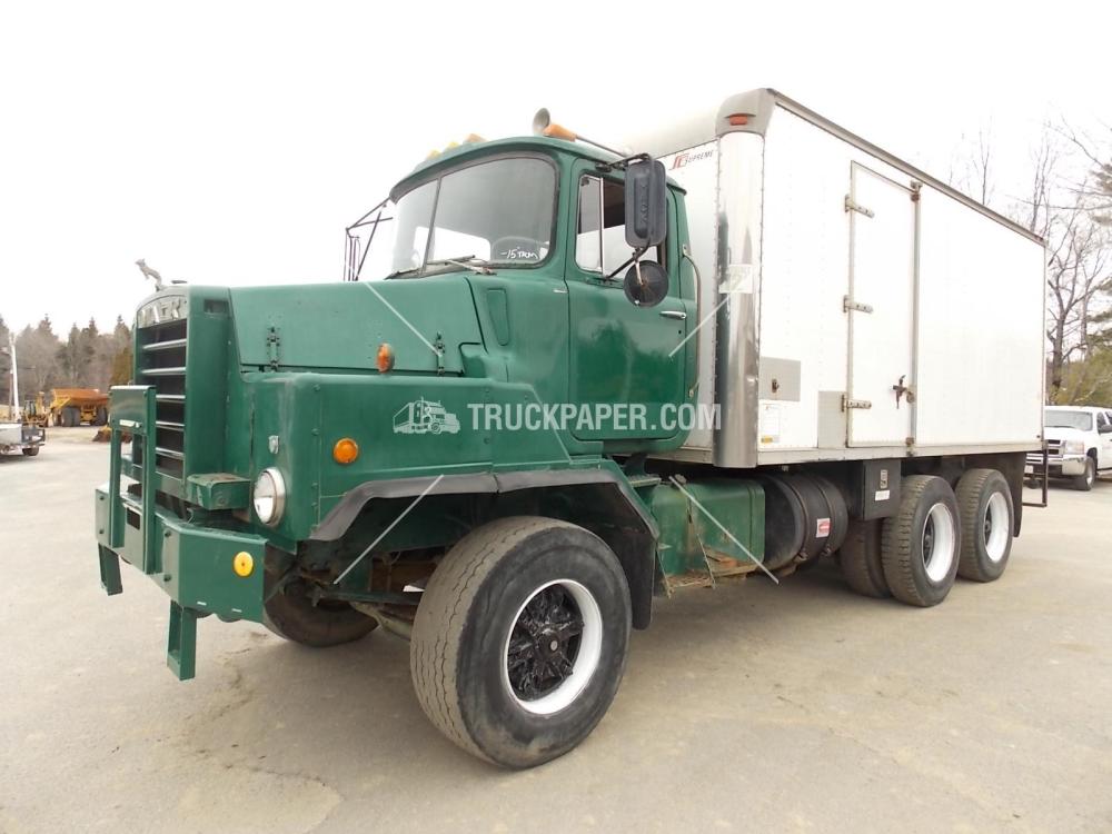
Uggh... I even couldn't imagine such state of things. Definitely wouldn't come check it out if even have US visa open at the moment. Thanks for sharing. I like C-models and tandems especially. The chassis looks solid judging by the pics. The truck may be fixed or restored but it seems better to use another cab than weld patches here and there in the existing one.
-
Yup, that animal would make any collector proud of having it. And just a pleasure to see.
-
Paul, your post confused me definitely! I couldn't put a like and a laugh smile together!
-
Youtube version worked fine for me. Although I don't see the original file, probably need to download it first and I didn't. Oh, just as Paul said above. Cool movie! Air start is absolutely uncommon feature on my side of the pond. What I thought to myself was it's nice to have a running Mack. And also nice when you have a bit of time to run it
-
Anybody toss a couple of pics from the ad please. I'm not going to get rid of 5K but would like to see the bucket. Facebook is banned in my neck of the woods.
-
Not really. Something between 2-1/2" and 3" I belive. Can measure them if really needed.
-
Guys in Iran make them new of stainless steel. Not almost the factory look. And sure not a place you'd easily purchase them from.
-
Aussie Truckin' Pics..
Vladislav replied to Hayseed's topic in Antique and Classic Mack Trucks General Discussion
Almost out of likes for now, thanks for posting these beautiful pix. -
B-21 Fire truck
Vladislav replied to MorrisMe's topic in Antique and Classic Mack Trucks General Discussion
The truck has fender extensions the way it was made to B73/75. The cab sits further back than a standard B61 so the steering column has to be different. Probably the same style as used in B73. -
The talk is about DM's, right? The reason I point it out is steel nose RD's and RM's seem being in production longer.
-
That's one good question I don't know the answer sorry but would be interesting to know. Probably the older TRXL and so. I'm not ready to tell the year T200 series came into production. With the end of the line of Cruiseliners in 1983 there might be a gap in time. Physically I see no trouble fitting T200 onto Mack engine flywheel housing. Rear mounts could be made of thick sheet metal and welded as even Mack did for some trannies. A shifter unit at the top of transmission may be an issue. What Cruiseliner has doesn't look the same as a MH. I don't know what is used on MR's or other later Mack cabovers equipped with T200 trannies. Worth to point out the shifter on the top of T1078 in my Cruiseliner has "Eaton" (not "Mack") cast into its hosing.
-
Buying another B-81SX
Vladislav replied to AMGeneral's topic in Antique and Classic Mack Trucks General Discussion
A barn find definitely! The frame rail pack looks very good. Hopefully the sheet metal is also solid and would only require cosmetic fresh up. -
H Model Restoration
Vladislav replied to h67st's topic in Antique and Classic Mack Trucks General Discussion
Looks great! That's definitely one of those moments we spend months of work to enjoy for a few minutes. Ok, you can pull it in time for a quoter an hour. Or for a few hours, days or weeks -
B-21 Fire truck
Vladislav replied to MorrisMe's topic in Antique and Classic Mack Trucks General Discussion
As long as you have the 1st truck in much nicer condition I would try keeping the 2nd one in the as is condition if I were you Looks like too much of labour to bring it back to life but it's looking cool with these greeny spots! Sure just a thought. -
My guess is the relief valve bypasses the fluid when you reach the turn stops. You continue "turning the wheel" so directing the gear to continue turning. What means applying pressure to the piston. But piston (together with Pitman arm etc) can't go since the knuckle is against the stop. So pressure doesn't have a way to go and would blow the lines. It opens the relief valve instead and bypasses back to the tank.
-
Yup, now it's a "double-historical" artifact. Probably's going to be a new Christmas item. I didn't know the story behind the scripts though. Now I understand it better. Or maybe I just wasn't English-understanding enough at the time I first saw the pic and read the conversation?...
-
Sorry to hear about the cat. Probably it was just the time for her to travel to cats heaven. Sure nobody knows for sure. The legs and breasts look very attractive. Real mouth water makers! And that wooden thingy partly closed by the bush - isn't that a ladder Mr.Grinch used to crawl onto the roof?? Thanks for posting.
-
Great!
-
Buying another B-81SX
Vladislav replied to AMGeneral's topic in Antique and Classic Mack Trucks General Discussion
Congrats on the addition to the fleet! Sorry I'm out of likes for today. And eager for the pictures. -
connecticut DMM 600
Vladislav replied to mechohaulic's topic in Antique and Classic Mack Trucks General Discussion


BMT Forum Logo
