

Vladislav
-
Posts
8,089 -
Joined
-
Last visited
-
Days Won
79
Content Type
Profiles
Forums
Gallery
Events
Blogs
BMT Wiki
Collections
Store
Everything posted by Vladislav
-
Thank you for the answer. I guess it's also possible to rework the door skin a bit in the mounting area to fit Chevy handles if you do that before painting the doors. Not the best approach to modify parts the way you wouldn't be able to install the original ones in place in the future. But could be done.
-
Cruiseliner Transformation
Vladislav replied to cruiseliner64's topic in Antique and Classic Mack Trucks General Discussion
Big job! Keep on going! I'm pretty sure the result will offset the efforts. And as you do it it will be seen very soon on my mind Of the brake shoes and drums my way would be keeping them in place and forgetting about them for at least 50,000 upcoming kilometers. You will doubtly make that much driving to shows and other events for fun. So those shoes have very good chances to serve for the rest of the truck's life. Maybe even more -
I saw a B-model at Macungie show fitted with similar chrome Daytons. Looked sharp from a distance but up close they were a big trouble with rust pitting all the way around each rim in the cavit area. The stampings contained "Made in China" letters. Big shame to spend some $$$, fit the wheels on a nice truck with new tyres and get such the "surprize" in a few years.
-
So those mounting plates you made are unseen from the outside?
-
Mack parts prices
Vladislav replied to Mack_man's topic in Antique and Classic Mack Trucks General Discussion
Of what I noted people are usually look for LH stack mount to arrange dual exhaust. This way I wouldn't surprize if there's really low interest on the basic RH mount since no much persons need it. Just a guess, not sure exactly. Also if I'm not wrong RW1 and RW2 stack mounts are different. Shipping options/possibilities influence success of a sell either. -
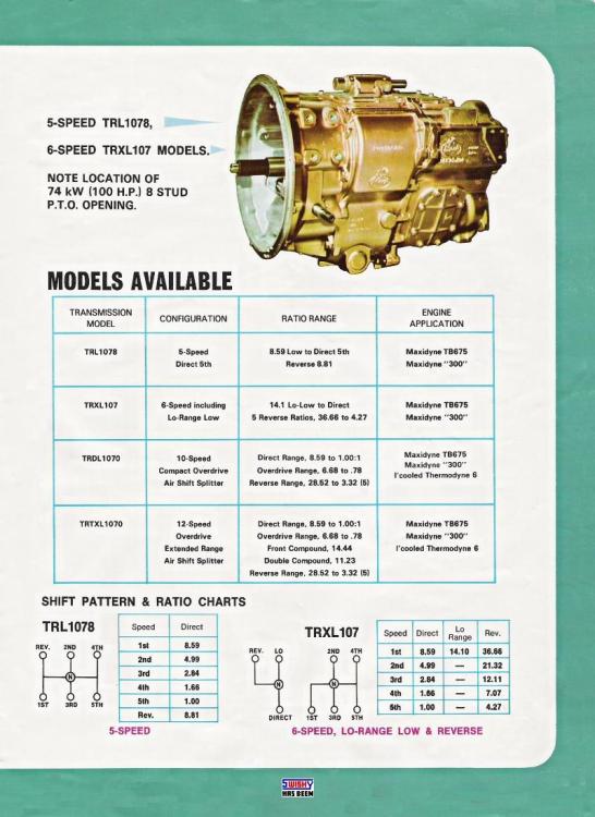
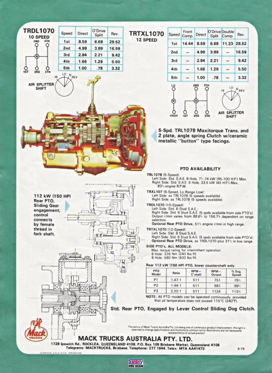
T2050, T2060, T2060A "compact" 6-speed, T2070, T2070B 7-speed multy-speed reverse, T2080, T2080B, T2090, T2100, T2110, T2110B, T2130, N2130B, T2180, T2180B - those which are known to me in T200 series. Each would have to have its special sticker. Speaking that older T100 series you mentioned both 6-speed and 12-speed had similar main box (of 5 speed). So that's the reason for similar sound they produced.

-
Update on the B Model Restoration
Vladislav replied to Derrico's topic in Antique and Classic Mack Trucks General Discussion
Nice! Keep on moving! -
Great reading Paul! Keep on going!
-
Those steer wheels are tube type and steel lock rings are painted white. You can see a gap at the split point on the photo. Cool job done to them and cool looking truck.
-
Looking the under the hood picture its frame rail more tells that's a RS not RL. Probably RS600L with just some alu attachments.
-
It seems to me such the swap would be easy. E6 were both equipped with T100 series and T200 series trannies. At least I have one 2V E6-350 with T1078 5-speed and one 4V EM6-300 with T1070 (or so) 6-speed. And two 4V E6-300 and 350 with T2070 and T2090 respectively. Ok, one more sample - 2V EM6-285 (with tip turbine) and T2060 6-speed. As I could figure E6 crank shafts were similar. IDK if there were mods over their front ends for possible PTO attachments but rear fit of the flywheel is similar in the most (all?) cases. Of trucks I have T100 trannies were arranged with 14" clutch (and a flywheel for it) and T200 mated to 15'5" clutch (with specific to it flywheel). I have no idea could the clutches (with flywheels) be interchanged between T100 and T200 trannies but it may be even possible since both tranny families had 2" input shaft. T300 series looks very similar to T200 but I didn't investigate actual differences. There was one interesting unit for sale locally but before I arranged the deal it had gone to scrap. So no experience was achived. One mote point to check out is the flywheel housing. Basically all must fit every E6 engine block and have similar (SAE #1?) transmission fit. But of what I noted there were multiple styles cast both of iron or alu with different rear crank seal housing (separate or unified) and some could have rear mounted PTO fittment. But overall it looks to me the most variants should serve regarding their positioning on engine, fitting every Mack tranny of the years and accepting 14" or 14,5" clutch. Those older single countershaft transmissions had different fittment to the flywheel housing. Not all probably but many had two big bolts (or studs) over the top of the mounting circle to the engine. And I wouldn't be surprized if even those old motors could be coupled with T200 series trannies if needed flywheel housing is installed. Sure worth to point out clutch drive and prop shaft fittment must be kept in mind. TRD67/72 were push type clutches for example. But all T100, T200 and T300 were used with the pull type.
-
Wicked but cool picture. That bulldog might fight an avarage hog. Is that his artwork?
-
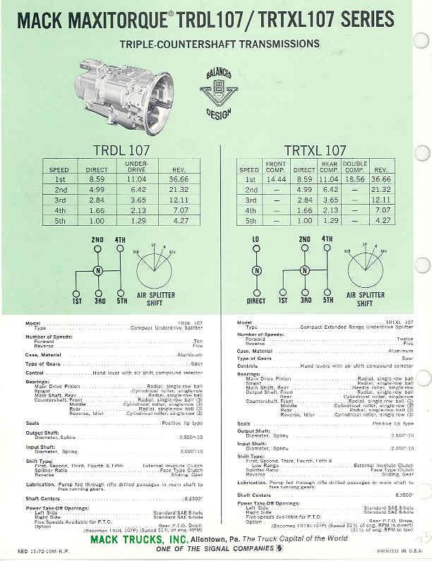
Yes, as said above. 40 years is a large time frame. In late 40's to early 60's and possibly even later Mack had two main families of transmissions - T67 and T72. Both with a single countershaft. Each series conteined basic 5-speed units and with a compound box attached was offered in Duplex (10-speed), Triplex (15 or so speed) and Quadriplex (18 or 20-speed) units. Than in the late 60's or early 70's the next generation with 3 countershafts came on the market. They were basically called T100 such as T105 or T106 for 5 and 6 speed with variations of markings such as T1078 (for 6-speed(!)) and also TRD's for Duplex and TRT's for Triplex. Than later in early 80's that generation was refreshed with newer design T200 series (also 3 countershaft design). Those were T2050 for 5-speed, T2060 for 6-speed and the same way up to T2180 18-speedy unit. Ok, in 90's next gen T300 took place which may be found taking place in later series RD or DM trucks. Each of those mentioned and unmentioned transmissions had its special shifting diagram plate. In the late 70's and further those were stickers. And in earlier times metal plaques were used attached to cab sheet metal with screws. Also some (probably many) trannies got shift diagrams of different styles during the years and worth to point out every sticker/plaque had its unique part number marked on it since all they were original Mack spare parts. During more than 10 years I used to keep photo's of every shift pattern sticker/plate I saw on the net or on a real truck. And now I would doubtly count 1/20 of all shift patterns Mack used during those 40-50 years. So what you're going to do is a big deal.
-
Upps... Looks like the life goes on. Or goes by?
-
Marriage
Vladislav replied to Vladislav's topic in Antique and Classic Mack Trucks General Discussion
Yes, they have. I was lucky seeing the truck in person when I had a chance to visit the museum in 2018 (many thanks to Doug Maney for the appartunity) I even have a little bit of relation to the truck. Once the museum crew initiated the restorations they contacted me on possibility purchasing an oil filter housing. The reason was I also owned a NM (and own it now) and had requested the built sheet for it previousely. Unfortunately I didn't have the needed part so I asked my Dutch friend who was reacher than me on Lend-Lease stuff. Ended up he donated that filter housing to the museum and the deal was done. There also was a thread on the forum on how that truck was purchased (actually - saved) from a certain facility before it took its way to the museum. I doubtly could find that post but had saved pics from there.

-
Marriage
Vladislav replied to Vladislav's topic in Antique and Classic Mack Trucks General Discussion
Thanks Larry! But you have a road ready classic truck. And I still tinker, tinker, tinker... -
There was a member on here who was restoring a AC in GB. His name was also Paul if I'm not wrong. But he didn't show up on the forum for a while. He also was taking care of two LFSW sleeper cab trucks which were previousely stored at a certain estate in Schotland (and became a really poor shape there).
-
That red truck on the pictures looks really nice and too probably will find a new owner if that's the plan. Of the value a few Bulldogs showed up for sale during the last 10 or so years I kept my attention to the subject. Complete units were priced in a range of 10-25K. But that's a very avarage figure and some more passed years could do correction to it also.
-
There are a few in Europe, mostly (or all?) former WW1 trucks supplied to France. One nice restored example is in Jisk Automobile Museum in Danrmark. Another one in about the original condition was stored in Normandy, France. But if I'm not wrong it got a go to another location. There also might be a few in GB.
-
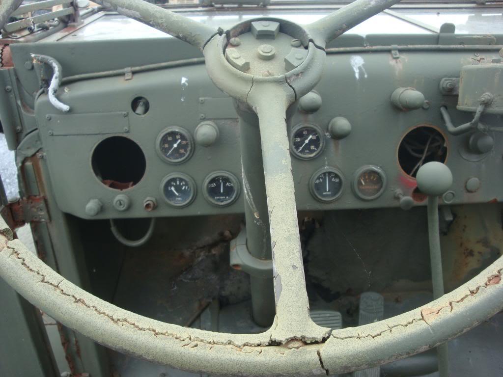
R model Dashboard Repair
Vladislav replied to jervn4's topic in Exterior, Cab, Accessories and Detailing
There were two kinds of those dash panels along the years. One style was plastic base with foam and vinil lamination, as described. The other one and the later one was solid plastic parts. ABS or so material. They were painted beige and gray metallic after a certain year. Those foam parts and solid parts seem interchangeable. And solid ones are much more steady and easy to fix (glue-fill-paint). I doubt there's a good way to fix foam conteining dash parts into or close to their original shape. There are laminating films with surface similar to automotive dash material (to repair or maybe even fabricate dashes?). But you doubtly could build up a layer of foam even enough to laminate it or glue up with anything. So on my mind two possible ways of fixing exist. Finding good used later style solid plastic parts and paint them over. Or bringing any style parts into upholstery shop to be furnished with leather or kunst leather. I personally took that second route. And those my dash parts are taking place at a upholstery guy for 4 or 5 years now. Along with a roll of covering material. Vlad -
Happy Birthday Mackey58!
-
Why not? We are hi-jacking the thread. Even I would make a serious offer of $1000. But too afraid the dog sledge routes are closed due to the sanctions.
-
Unfortunately I don't see any 'book pics. Only the one at the top of this post. I'm not a big specialist in early Mack V8's. But I think 325 and 375 have similar appearance. And 864 had stamped steel valve covers in compartion to 865/866 with cast alu ones. But it's possible there were option on those covers or mods during the production years I don't know. R-model frame rails (F600) have light decline toward the front end. F700 rails had steeper decline. But they're also belly-fished (or fish-bellied?) and have incline at the bottom side of the rail toward the front end. Presence of that torsion bar indicates it's F600. But I'm not 100% sure. Mike would say the truth. But he unfortunately wouldn't.
-
Maybe 866?
-
No. R700 chassis has similar config to R600 chassis but of higher section and of thicker sheet (3/8"). F700 chassis has different shape of the front portion, actually its own specific shape as long as I could observe along other Mack models. Maybe CF firetrucks had similar rails IDK. At the same time if I'm not wrong F700 had the same (light) section of the rails at the rear as R600 - 9" tall and 1/4" thick. That's standard section for basic B-models and a few other Macks of the era. Worth to point out we talk about Eastern R's and F's. Western R700 (RS/RL700) like your truck have straight rails with constant section front to rear. I don't have specs for those frames, would be interesting to learn the sizes. There were also FS/FL (700?) produced at Hayward factory. Which also had straight frame rails, the most probably similar to what was used in RS/RL700.


BMT Forum Logo
