


Full Floater
-
Posts
394 -
Joined
-
Last visited
Content Type
Profiles
Forums
Gallery
Events
Blogs
BMT Wiki
Collections
Store
Everything posted by Full Floater
-
Thanks. Curious as to what is better about the rear mount? Is it a stronger or more reliable location to mount the PTO, rather then the side?
-

Foot valve plumbing questions.
Full Floater replied to Full Floater's topic in Air Systems and Brakes
Thanks. So all the delivery ports are the same, and all the supply ports are the same, correct? Just a matter of where the line and fitting fits best? -
Foot valve plumbing questions.
Full Floater replied to Full Floater's topic in Air Systems and Brakes
Exactly. Prime example of cutbacks. Made in China for sure -
Foot valve plumbing questions.
Full Floater replied to Full Floater's topic in Air Systems and Brakes
I think figuring out which port is supposed to deliver air to the foot valve, would get me going as I would then be able to see which port exhausts air when the pedal is depressed for the front service brakes, as for the rear maxi's, I suppose there would also be air at that port for the foot valve to "release" to apply service brake to the rear -
Foot valve plumbing questions.
Full Floater replied to Full Floater's topic in Air Systems and Brakes
Definitely. I avoid plastic/nylon lines when I can and try to stick with fabric braided lines and JIC style fittings. -
Foot valve plumbing questions.
Full Floater replied to Full Floater's topic in Air Systems and Brakes
It actually doesn't, but I got a diagram on the www. Such as this one http://www.newtruckspring.com/wholesale/bendix-277863x-e-3-brake-valve/ -
Picked up a 76 600 western that runs and drives but the owner died a few years back, however; the foot valve is out of it, with a new Bendix E3 sitting on the floor to replace it with. Im wanting to install it on the spot so I can drive the truck home. I've always just placed the old lines on to the new foot valve as they came off the old valve, not really know which port is supposed to do what. Can't do that with this one as the old valve is gone. -Does the supply air for both front and rear service brakes come from the "delivery" or "supply" ports on the foot valve? -Also, which port is supposed to supply air to the foot valve itself? This should steer me in right enough direction to get me going without too much crossing lines.
-
Not a smaller ID seal needed when running a speedi sleeve?
-
I have yet to speak with a drivetrain shop to see what they might know of, as to what's out there or what can be made.
-
Awesome! Thanks for sharing the video and your findings. Can't wait to watch it.
-
I notice this on all my Mack E6's. The gov springs in general seem to be a weak link on these and can be very touchy. I bet the slight load, or lack there of it when the compressor is off, throw the gov springs off slightly. I wouldn't worry about it much, although it can be a bit annoying. But hey, it's way better then a new truck with a check engine light
-
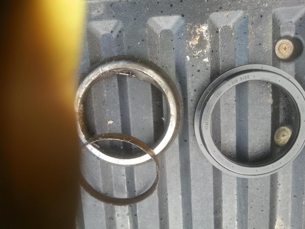
Stemco 2 piece vs Voyager. The voyager went in nice and smooth and seemed to fit well. Running Lucas Hub oil. Will see how it lasts.
-
Yes, I'll take some pics. The Stemco number is 320-2137, crosses to a Voyager 383-0164. I did manage to find some early seals at Finditparts online and ordered them for on the shelf for later. But the Voyagers are the only thing I can get here locally at any of the jobbers
-
I wish I had an Allied Bearing Co, near me. ....or anything good for that matter.
-
Yes I did mean the steer axle. 1975 R with 18.000lbs front. I will have a close look for that dowel pin hole, thanks! I just pulled the old wear ring off to get measurements and such to confirm the right new seal, will get back at it later today
-
I have been struggling to find Stemco 2 piece seals lately. Found a set for the rear axle on the s/a R that im putting together, but nothing for the front. So Voyager it is. We'll see how it goes. I don't know what's best these days but Im only familiar with the Stemco's on the old iron that I have. If Voyagers last, well I guess that may be the ticket. I assume they are easier and quicker to install, and they seem to be available
-
Not trying to hyjack this post, but my personal beef with them is the extra space they take on an application that's space limited. And the added moving part (driveshaft), which is kind of a moot point, but it's always nice to eliminate extra moving parts when possible
-
Good question. Im casually on the lookout for something for a rear mount pto on a 6 speed. I'll report back if I find something
-
Where to source clutch cables
Full Floater replied to Full Floater's topic in Engine and Transmission
Mine showed up today AND it was the right one!!! That's always nice. I managed to fit the spray nozzle of of Fluid Film can into the cable sheath and held a rag super tight around it and gave er all the way and got Fluid Film coming out of the opposite end after a while. It was a little messy but that was a quick and easy way to pre lube the cable! -
Where to source clutch cables
Full Floater replied to Full Floater's topic in Engine and Transmission
I will certainly keep the cable on the shelf for the day that I need it! Thanks for you input on lubing the cables. I think that's an important step to longevity and reliability. I used to coil an entire cable and place it in a bucket of oil of some sort, and let it sit for a day or so. Not sure if it did anything, but I don't think it hurt. -
Where to source clutch cables
Full Floater replied to Full Floater's topic in Engine and Transmission
Sounds like my closest dealing thinks they found the right one. It's on order....we'll see what happens -
Where is a good place to start looking for a clutch cable replacement for my 75 R600? Mine's not broken, just want to stay ahead of that game. Is this s dealer item? How do I measure it to know what length this particular cable is. Regards
-
Thanks very much everyone. One more question, which perhaps has already been answered and I missed it? ....but is there an option for a married pump to mate to the rear mount existing pto? Since it sounds like a wise idea to leave the pto itself, alone.
-
Wow! MANY THANKS for taking the time to write that post. All of which is news to me! I might want to re-think this whole ordeal
-
I am wanting to have a more compact setup and re-purposing the truck and need the room where the remote pump currently sits. I'm curious as to why you prefer the rear mounts. I honestly don't know the difference between the two


BMT Forum Logo
