


Geoff Weeks
-
Posts
2,559 -
Joined
-
Last visited
-
Days Won
7
Content Type
Profiles
Forums
Gallery
Events
Blogs
BMT Wiki
Collections
Store
Everything posted by Geoff Weeks
-
Connecticut Construction Trucks
Geoff Weeks replied to BKrois's topic in Antique and Classic Mack Trucks General Discussion
Looks to be 4x8, neither front hub looks like it is a driver. -
If you can, go back with something brushless! I don't know how many of those L/N JB series I have kicking around. I always replace with something without brushes.
-
You didn't say what engine you are working on, but; My experience: Heating several times, trying to break free, working back and forth once it did, still ended up with a cracked casting. From then on, Drill them out progressively until just under the thread size and collapse them in. Labor intensive but safest.
-
PM sent to Stutz
-
I got a bunch of stuff, mostly IHC, that when one failed, and I could track down a source, I would buy more than one, often they were being sold off as a "lot". I have things like horn button brush, that most don't have or replace, until you needed, to, then can't find them. I'd love them to go to somebody who could use them, but the hassle of selling on Faceplant or Ebay, only for somebody to want to return them, on my dime when they mis diagnosed, or just didn't want it, isn't worth the hassle. That speedo is going for anywhere around $100 and up on ebay, I can't remember what I paid for it, and I can't give it away? Kinda mind boggling!
-
I got to say, this is aggravating. 7 months ago he asked about a speedo, at that time I said he could have it for free, just pay the shipping. Nothing for 7 months, than asks if I still had it. I replied again I still had it, Then he wants to know if i have the female connector, and how much. I go dig out the harness and find it isn't the right connector, but list places he can get it I again offer it for free, he pays the postage. and add in how it is currently set. Then again, I get radio silence? People ask why I don't sell my store of parts? Hell, I can't even give them away! It is getting not worth the trouble. I found a box, found some pages on the internet that would help with the wiring. And yes, I've checked, he has been on the site since my last post. I am generally free with my time, but when someone asks me a bunch of questions, and then nothing?
-
I liken my K-7 to driving my 9670 with about 118K on it. It is foot to the floor, and when you hit a hill it pulls down (from 3000rpm) to around 2000 and just hangs in there. No point downshifting until it pulls below ~2000. It means, while it will do 55-60 MPH on the flat, when your pulling hard you drop down to around 40. Driven in the heat, with the windshield and side windows wide open and driven in the cold (-10) for 400 miles. Not as comfortable as more modern trucks but keep going.
-
The only thing I would change is the transmission ratios. I find the large leap from 3-4 and the short 4-5 not to make the best of the power the engine can produce. I much prefer even steps, and higher rear with direct top gear. The lack of gearsets for the rear, leave that pretty much a pipe dream to make any changes.
-
You already own something better, IMHO!
-
Connecticut Construction Trucks
Geoff Weeks replied to BKrois's topic in Antique and Classic Mack Trucks General Discussion
Up until Elon destroyed Maxwell, my preferred solution for 24 volt crank/12 volt run was a 24 volt ESM from Maxwell. Charges on 12 volt, provides 24 volt cranking. Completely "hands off" split charge ( transformer/rectifier) alternators and S/P switches are distant 2nd. Too many can't figure out S/P switches, and there are failure modes that leave the truck "dead". T/R alternators are ok but the battery banks don't age equally. I don't consider 24 volt crank, 12 volt run, 24 volt systems at all, they are 12 volt systems that are paralleled for cranking only. I had a service van fitted out with two 8D's down under the body and a S/P for charging. It could start a 24 volt bus with flat batteries. It could also jumpstart 12 volt vehicles. -
Connecticut Construction Trucks
Geoff Weeks replied to BKrois's topic in Antique and Classic Mack Trucks General Discussion
Only trailers I saw that were 24 volt were either military or gravel screen plants made in Europe. COW are small, single axle things aren't they, I am surprised they would overload 18 ga wire with only a few lights? Cars of the vintage we are talking only had 16 ga at most, I think most were 18 for the lights. 18g can carry 10 amps at least, how many lights did these things have? -
Connecticut Construction Trucks
Geoff Weeks replied to BKrois's topic in Antique and Classic Mack Trucks General Discussion
On stuff I did 99.9% of the wiring was more than what was needed for 12 volt. I can't think of a single time we needed to change the wiring size. Before the days of solid state "converters" Vanner battery balancers were the only option, for 12 volt supply. Some stuff could be put in series, but not headlights. The must be able to operate with one light blown. Back in the 80's the Vanner's were big clunky things. Motor coaches were 24 volt almost from the beginning. headlights were the main thing that was needed for DOT, the rest didn't matter what voltage the bulbs were. Tail light, brake light, turn signals all had to be there and work, but the bulb voltage is irrelevant. It only mattered for headlights because the bulb also contained the lens and dispearsment pattern. Rest of the required equipment (wipers, defroster etc) didn't matter either. Only time 24 volt becomes a problem is if it has to tow a trailer that interchanges with 12 volt tractors. -
Connecticut Construction Trucks
Geoff Weeks replied to BKrois's topic in Antique and Classic Mack Trucks General Discussion
I doubt 24 volt lights, At that time period no sealed beam 24 volt lights met the DOT regs, Military headlights were sealed but didn't meet the other requirements for light pattern. I know, I had to convert 24 volt stuff to DOT regs. -
More than likely it is. I had IHC's and when I sold the trucks, the manuals went with them. I retained one parts manual and thought it had the settings, but it doesn't Should be the same for all TrekStar speedo's 16 tooth is the most common input, but there were other variations used. My '84 parts truck had a "tone ring" in one of the rear hubs. So far, I haven't heard from him where to send it, so it sits in a box.
-
I no longer have the service manual with the calibration settings and wiring. You'll need the calibration settings for your application. IIRC it is set for a 16 tooth transmission "gear" and 501 rev/mile tires on a 3.73 rear gear.
-
No luck on the plug, the wiring harness I have was for an older truck with an early Motorola speedo. You can order the plug from here or many other places: https://brillman.com/product/4-cavity-packard-56-series-female-terminal-connector/?srsltid=AfmBOoqYbrEyZ8pCtYr_O9nAQ5DW_qNtIp72twqfn7Cw0comsmdrD9vId3o&gQT=2 along with terminals: https://www.zoro.com/grote-terminal-56-series-16-14-ga-pk10-84-2013/i/G9793869/?utm_source=google&utm_medium=surfaces&utm_campaign=shopping feed&utm_content=free google shopping clicks&campaignid=21460994854&productid=G9793869&v=&gad_source=1&gclid=EAIaIQobChMI3vS6kdqniwMVtzUIBR3taznaEAQYAiABEgLa4_D_BwE&gclsrc=aw.ds But I bet NAPA could get it all also. PM me with an address, it is yours for the postage.
-
Ah, no Packard "56" style
-
I might, I'll have to look. Just a std Packard plug. I have an old wiring harness, I'll see what is on it.
-
Latest find....
Geoff Weeks replied to Freightrain's topic in Antique and Classic Mack Trucks General Discussion
There is a reason you don't see the air to air mounted behind the radiator! I'd do whatever it took to get outside air to the tip turbine. -
Latest find....
Geoff Weeks replied to Freightrain's topic in Antique and Classic Mack Trucks General Discussion
12515 had a lowest ratio of 13.87, but now you are comparing apples to oranges, you loose any O/D so top end is off. Any way you cut it, a 13 has more to offer than a 12 (15). The 13 spds had bigger jumps in low range, where it is less important, and smaller jumps in high range where it really helps. The RT12513 has an U/D splitter The RTO12513 has an O/D splitter, the main box is the same. The RT12515 is direct main the RTO 12515 is an OD main. I will agree that a Cat can handle a slightly bigger jump in ratios but it doesn't loose anything with smaller jumps. -
Latest find....
Geoff Weeks replied to Freightrain's topic in Antique and Classic Mack Trucks General Discussion
Your losing me, I thought we were talking on hiway and O/D 15's? RTO 12515 has it's lowest starting gear (deep reduction) of 10.93, compare that to a RTO12513 which has 12.5, the 13 has lower starting and closer steps, it has less of an O/D which mean less power lost to heat in the top gears. Front trans is in direct, back box in O/D 13 has between 19 and 15% steps the 15 has between 27 and 30% steps. I know which I would choose! The 15 provides neither lower starting nor closer steps. -
Latest find....
Geoff Weeks replied to Freightrain's topic in Antique and Classic Mack Trucks General Discussion
An Eaton 15 has 12 usable ratios, and those "extra" two over a 10 speed are lower than the lowest ratio's in a 10 All the other available ratios in "deep reduction" are mirrored in the low range of the trans. A 13 has 13 useable and that is if you don't count "funny gear" (low in high range), with better steps between gears. -
Latest find....
Geoff Weeks replied to Freightrain's topic in Antique and Classic Mack Trucks General Discussion
I have both 13's and 15 over, I wouldn't have a 15 if I could avoid it. Lots of seat time with both, so I think I can speak from the point of experience -
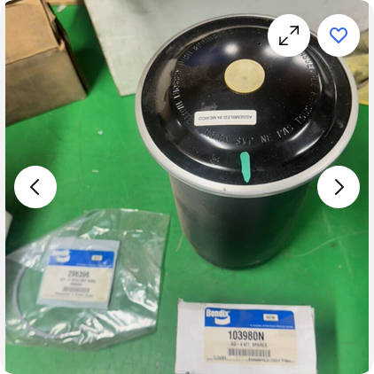
The pale yellow disk in the center of the cartridge often gets hard and breaks apart. So if buying off of ebay or other such source, be very careful that the valve (yellow disk) is intact and pliable. While your waiting for the parts to come, you can add a check valve at the wet tank to keep it from blowing off all the air in the wet tank.
-
Yes, but you have to take it all apart to get to it. I would also replace the desiccant cartridge at the same time. I be willing to bet the check valve on the top of the cartridge is bad also. The AD-4 is the best, but hardest to service air drier out there in my opinion. It was all I ran and I had air start, never any moisture in the tanks when I would check them.


BMT Forum Logo
