


Geoff Weeks
-
Posts
2,434 -
Joined
-
Last visited
-
Days Won
7
Content Type
Profiles
Forums
Gallery
Events
Blogs
BMT Wiki
Collections
Store
Everything posted by Geoff Weeks
-
Wiki has a pretty good definition.
-
Old Jake brake thread. Brake saver retarder question
Geoff Weeks replied to BronsonA2150's topic in Engine and Transmission
In OTR trucking in this country the weight would be a problem. In buses you likely wouldn't have a problem with an extra 700 lbs, firetruck not a problem, garbage packer maybe or maybe not. I guess that is why they weren't a big seller here. In a country where far too many drivers look a a jake as a noise maker to startle people, they would have no attraction. Your likely looking at a similar weight penalty with a Cat brakesaver, and they were never very big sellers either. With the fact the engine can be ordered OEM with the brakesaver likely made them an easier sell then the Telma which would be a separate sale. -
Old Jake brake thread. Brake saver retarder question
Geoff Weeks replied to BronsonA2150's topic in Engine and Transmission
The ones (Telmas) I was around were on LP fueled M.A.N.'s so had a throttle and therefore would not work with a Jake. However if you could justify the weight there is no reason they couldn't be used with an engine Jake as well. Some of the heavy hauler had 3406's with both Jake and Brakesaver, as weight is never an issue when every load is a permit load. I don't know how much they weighed, but there was big rotor on the output (transmission) or input (rear axle) and a stator that surrounds the rotor with a series of electro-magnets in it. So lots of copper and iron. Brakesaver used engine oil to act on a turbine wheel between the engine and clutch. Retarding energy was turned into heat in the engine oil. Cats with Brakesavers have bigger oil coolers then those without. When Cat used an injection pump and nozzles in the head, there wasn't a handy injector rocker to time the Jake like there was with Cummins and 2 stroke Detroits for optimal valve opening. Cat Jake's of that period used an adjacent cyl exhaust rocker to trip the Jake, but its timing wasn't ideal so the retarding wasn't as good as it is with common rail engines. So that is why the Brakesaver hung around until the changes over to common rail fueling. At that point the timing came from the injector rocker, like Cummins. By the time we got the LP buses, mostly the Telam's didn't work, we had enough to do to keep the buses running and Telma's weren't needed in Chicago like they were in Austria where the buses came from. I think may be 1 out of 4 or so worked. Likely needed something simple, but there was never time. -
Old Jake brake thread. Brake saver retarder question
Geoff Weeks replied to BronsonA2150's topic in Engine and Transmission
Telma's were more often found on buses. 1) they are silent, so not to alarm passengers, 2) they are heavy. Buses usually have less trouble keeping on the good side of weight law. 3) they are electric and can suffer from the gremlins common to high current electrical devices. Cats "Brake saver" was hyd with engine oil being the medium used. It was heavy when compared to a Jake or Macks retarder. The reason for it went away when Cat (and others) changed to common-rail injection. -
Not anchored to footings?
-
Closing off the back end will help as well as keeping debris from blow in. Cables in an X with turnbuckles to tension will do a good job as well. Closed back end with X cables would be the best.
-
2000 Mack rd688 e7 air compressor help
Geoff Weeks replied to Moparmike's topic in Engine and Transmission
Another thing to consider, if it did push significant amount of coolant through the air drier, then a complete service of the air drier is warranted. You said you drained the air tanks, was any antifreeze found when they were drained? -
2000 Mack rd688 e7 air compressor help
Geoff Weeks replied to Moparmike's topic in Engine and Transmission
It sounds like a blown compressor head gasket. One thing that can cause that is a coked up discharge line between the compressor and the air drier. Make sure to check and see how well air can blow through that line so you don't blow the head gasket on the new compressor. When you have the compressor off, disconnect the line from the compressor at the air drier and use an air gun to blow through. It should blow with almost no resistance to air flow. -
Honest, and you can sleep well at night if he still goes forward with the purchase.
-
I would say in the country, there are a whole lot more people who are center left, that don't like what they are seeing and not "left wing". There are extremest on both side of center, and being on "the other side" doesn't make you an extremest. Too often its "if you don't agree 110% you are the "other side' at 110%, and that just isn't true.
-
The problem is Jo-Jo already has an old IHC gas job. The big gassers are hard to justify to just take to shows. Nice, yes but expensive to insure, feed and register. His K-7 on the other hand, is of a size that you could actually used it for the occasional parts run or something. I have had a gas Fleetstar for a while before I parted it out. Only thing it got used for was a yard goat, spinning trailers around. My K-7 has done much more. I'm not knocking the truck at all, just that few can afford the luxury of a show queen that only goes to shows, takes up a lot of room, and the case of a 549 is expensive to run. Smaller antique truck can give about the same thrill and is easier on the wallet. It likely why so few of the bigger one survive. Other dog found it didn't fit him all that well either. There is a guy on another site that has one as a grain/farm truck. A little more options there to put it to use.
-
I hate doing burn jobs. Best thing I can recommend is finding a complete used truck that is similar and making one from the two. Even if you can find a "new" or even used cab, there will be so much other damage that will send you chasing after individual parts, it will drive to cost and time way up. Another complete truck that you pick all the small parts off of, make the job more attractive. Best of luck
-
Well if it goes into 2nd fine at a stop, that pretty much rules out clutch issues. Remember we can only comment based on what you tell us, only your eyes and fingers on the truck. Could be interlock issue in the shift tower.
-
I could be wrong. Just something to consider. My reasoning is thus: If there is drag trying to turn the input shaft, it is going to continue to load the gears/dog clutch, making them hard to separate. It is by no means definite, but if it goes into 1st grinding , it would point to drag on the input preventing it from coming to a stop. When shifting in to higher gears, both shaft are in motion the whole time (unless you are trying to put in 3 rd or 4th while standing still). Torque gets multiplied the most in 1st gear, meaning any input drag is multiplied by the 1st gear ratio. It would see a greater force then higher gears on the sliding (dog) clutch.
-
Does it grind or have any trouble going IN to 1st at a stand still? I am thinking about a defective pilot bearing here.
-
A fare lump of a stick
Geoff Weeks replied to mrsmackpaul's topic in Antique and Classic Mack Trucks General Discussion
O/D load violations can be staggering. If they can find a reason to "invalidate" a permit, fines go back to legal limits. Not for the faint of heart. -
I remember back in late 2007-2008 being in Idaho, filling my tank and getting a little cash and writing a check for 1 large. Clerk looked at me and said 'If the bounces it is a felony". Yeah, we've been there before, and it was right before a fall.
-
Neom: It is very simple, she went from being an asset in his eyes to a liability. I have no idea if he knew about the ad campaign and its costs before hand or not. He didn't care about the mess in MN or the citizens being killed or hurt. But make him look bad with a multi million dollar ad campaign and YOU are going to take the fall, not him. Waste fraud and abuse is in the spotlight, and you are going to take the fall. It wasn't Dem outrage that cause her to loose her job it was Rep outrage that did.
-
My understand, again I am open to correction, is the additive is a "salt" that plates the surface and is blown off the surface by cavitation only to be replated again. You see this "salt" as a white powdery substance on the liners, and anywhere where coolant has leaked and dried. Modern waterpumps use sealed ball bearings in a cavity that is protected from coolant by the face seal and weep hole (to drain any coolant that gets by the seal). I also know it is possible to "over treat" (and there are test strips to check for levels) and cause problems.
-
My understanding of coolant additives is they deposit a "sacrificial" layer that the cavitation bubble can act on, then it replaced by a new layer, saving the liner from damage. Filters remove any contaminates from the coolant. As the additive gets "used up" new additive must be added at intervals to maintain protection. It can be done by a "charged" coolant filter or in liquid form. That is how I understand how it works. I will say, taking apart an engine with a coolant filter and additive that has been maintained, compared to one that just ran coolant, you can really see the difference. I have added filters to my antique truck engines and see results in how well they cool. It takes a bit to "clean up" a dirty system, but short of pulling the engine apart, removing core plugs and hot tanking, it is the next best thing.
-
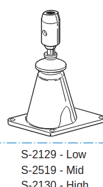
S2130 is a high tower "kit" (full assembly).
-
Here is the catalog: Levers-ControlsHD eaton.pdf
-
I have, but not with a 13 or 18 but there is no reason they couldn't be used. Vemeer uses a big Cat with a (I think) 9 speed Eaton on the rear to drive large "mud pumps" for horizontal drills. I guess it is cheaper and more compact than building a purpose built gear reduction on the rear of the Cat. I think it all depends on the output speed desired. The units I saw were brand new at the factory. IIRC it only used one gear and neutral as well as the automotive style clutch. It has been a few years but my memory is that it a plate over the shift rod that prevented it from being placed in other gears other than one it was supposed to be used.
-
Ill have to look for it, but somewhere I have Eaton shift tower catalog (pdf). Yes, they did make different towers which is not the same as different shift rods. The towers have a "spud" where the isolator and rod are attached.
-
I hope @kt_Engineer will be able to enlighten us. One thing about learning something, the more you learn the more question you think of.


BMT Forum Logo
