m16ty Posted November 28, 2018 Share Posted November 28, 2018 I don’t know if this should be in this forum or the driveline forum. I’m trying to mount a Fuller at1202 in my RD822SX. I’m planning on having rubber mounts on the back mounts, and mounting the front trunnion mount solid. There is just very little info to be found about how to mount a auxiliary. I did find a Spicer driveline publication that gave a little info. Where I sit now, both the main trans and auxiliary trans are sitting at 3deg tilt. To miss the crossmembers, the auxiliary is sitting quite a bit lower than the main trans, which makes my front driveshaft at a 6 deg angle. Spicer says that it’s best to keep driveshaft angle under 3 deg, but more is doable. I’m just trying to set this thing up where it runs smooth and make sure I have it mounted right. Does anybody have any experience with mounting an auxiliary and can share any insight? Quote Link to comment https://www.bigmacktrucks.com/topic/54908-mounting-an-auxiliary-trans/ Share on other sites More sharing options...
Ol2Stroker Posted November 28, 2018 Share Posted November 28, 2018 with the aux that low what would the rear driveshaft angle be? 1 Quote Link to comment https://www.bigmacktrucks.com/topic/54908-mounting-an-auxiliary-trans/#findComment-410199 Share on other sites More sharing options...
m16ty Posted November 28, 2018 Author Share Posted November 28, 2018 1 hour ago, Ol2Stroker said: with the aux that low what would the rear driveshaft angle be? Rear driveshaft angle is almost straight. As it is sitting right now, the rear output of the auxiliary is roughly the same height and location of the original carrier bearing. I think my current plan is to go ahead and mount it where it is, and I can always shim under the mounts to raise it if needed. Sitting level on the shop floor, the front rear has the capability to go up 5 1/2” before it hits the stops. If I raise the auxiliary much more than it is now, there is concern that the driveshaft could contact a crossmember, with the front axle in full articulation. Quote Link to comment https://www.bigmacktrucks.com/topic/54908-mounting-an-auxiliary-trans/#findComment-410207 Share on other sites More sharing options...
m16ty Posted November 28, 2018 Author Share Posted November 28, 2018 To make everything look better, common sense would tell you to raise the front of he auxiliary, to decrease the main to auxiliary angle, but the Spicer driveshaft publication says otherwise. The publication states that the main and auxiliary shafts should be no more than 1/2 deg within parallel to each other. Quote Link to comment https://www.bigmacktrucks.com/topic/54908-mounting-an-auxiliary-trans/#findComment-410208 Share on other sites More sharing options...
Freightrain Posted November 28, 2018 Share Posted November 28, 2018 (edited) I forget where I found the information for when I put mine in. Seems they wanted the driveline angles on the center driveshaft to be equal to cancel out. My motor was like 4* down, so I did the same with aux. Since I stretched the truck 5ft, it didn't hurt the rear driveshaft so much. I'd have to go measure, I think I kept the basic centerline the same height in the frame. It runs smooth, so I guessed correct. I know on lifted trucks, they rotate the rear axle upward to help eliminate u joint angle. I wonder if you could do the same? Edited November 28, 2018 by Freightrain 1 Quote Larry 1959 B61 Liv'n Large...................... Charter member of the "MACK PACK" Link to comment https://www.bigmacktrucks.com/topic/54908-mounting-an-auxiliary-trans/#findComment-410212 Share on other sites More sharing options...
terry Posted November 28, 2018 Share Posted November 28, 2018 1 hour ago, Freightrain said: I forget where I found the information for when I put mine in. Seems they wanted the driveline angles on the center driveshaft to be equal to cancel out. My motor was like 4* down, so I did the same with aux. Since I stretched the truck 5ft, it didn't hurt the rear driveshaft so much. I'd have to go measure, I think I kept the basic centerline the same height in the frame. It runs smooth, so I guessed correct. I know on lifted trucks, they rotate the rear axle upward to help eliminate u joint angle. I wonder if you could do the same? But on a tandem rear when you tilt front rear to change angle on front driveline you throw the short drive shaft out of alignment between rears. terry 1 Quote Link to comment https://www.bigmacktrucks.com/topic/54908-mounting-an-auxiliary-trans/#findComment-410221 Share on other sites More sharing options...
Freightrain Posted November 28, 2018 Share Posted November 28, 2018 Doh....didn't think about this having tandems. 1 Quote Larry 1959 B61 Liv'n Large...................... Charter member of the "MACK PACK" Link to comment https://www.bigmacktrucks.com/topic/54908-mounting-an-auxiliary-trans/#findComment-410233 Share on other sites More sharing options...
ranchhopper Posted November 28, 2018 Share Posted November 28, 2018 Im looking for an auxiliary trans if anyone has one for sale need it for a project it has a spicer direct drive five speed in it now and 50 MPH is top end. 1 Quote Link to comment https://www.bigmacktrucks.com/topic/54908-mounting-an-auxiliary-trans/#findComment-410244 Share on other sites More sharing options...
m16ty Posted November 29, 2018 Author Share Posted November 29, 2018 2 hours ago, ranchhopper said: Im looking for an auxiliary trans if anyone has one for sale need it for a project it has a spicer direct drive five speed in it now and 50 MPH is top end. I’ve got a Spicer 1241c available. Quote Link to comment https://www.bigmacktrucks.com/topic/54908-mounting-an-auxiliary-trans/#findComment-410268 Share on other sites More sharing options...
ranchhopper Posted November 29, 2018 Share Posted November 29, 2018 I PMed you. 1 Quote Link to comment https://www.bigmacktrucks.com/topic/54908-mounting-an-auxiliary-trans/#findComment-410274 Share on other sites More sharing options...
m16ty Posted November 29, 2018 Author Share Posted November 29, 2018 14 hours ago, Freightrain said: I forget where I found the information for when I put mine in. Seems they wanted the driveline angles on the center driveshaft to be equal to cancel out. My motor was like 4* down, so I did the same with aux. Since I stretched the truck 5ft, it didn't hurt the rear driveshaft so much. I'd have to go measure, I think I kept the basic centerline the same height in the frame. It runs smooth, so I guessed correct. I know on lifted trucks, they rotate the rear axle upward to help eliminate u joint angle. I wonder if you could do the same? It's my understanding that what you want to make sure of is that both transmissions are on the same angle. The way it was told me, is that any u-joint at a angle changes velocity each revolution, and that velocity increases the steeper the angle gets. What you want is for both u-joints to operate at the same angle, that is the front u-joint will change velocity a certain amount, and the rear u-joint will cancel it out, not passing the velocity change on down the line. The other thing you have to be careful about, even if both u-joints are operating at the same angle, is too much driveshaft angle, as there will be too much velocity change and cause a vibration in the driveshaft itself. Spicer recommends trying to keep your driveshaft angle less than 3 deg if possible , but does ok having steeper angles. They just say u-joint life will suffer some at angles above 3 deg. Right now I'm sitting at 6 deg driveshaft angle, which I think is acceptable, as you see steeper angles than that in some factory setups. Spicer also warns against putting your driveshaft at zero angle, stating that if the u-joint never flexes it will just wear in one spot and the needle bearings won't rotate around the cup. Without precision measuring instruments, I doubt you'd ever get it that close anyway. My only immediate issue I have now is rubber mounts. I've got the rear sitting on rubber mounts (borrowed off a military deuce engine mount) but am just planning on bolting the front trunnion mount solid. I hope I'm not making a mistake solid mounting the front mount. I'm kind of pressed for room on the front mount and the trunnion already allows the trans to rotate freely within the mount. Quote Link to comment https://www.bigmacktrucks.com/topic/54908-mounting-an-auxiliary-trans/#findComment-410283 Share on other sites More sharing options...
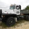
Freightrain Posted November 29, 2018 Share Posted November 29, 2018 (edited) Mine has the horse shoe collar around the front, and just a piece of like 2 1/2" angle across the back. Both are sitting on rubber mounts. I don't think mounting it solid would do it any good. Any frame flex would try to break the mounts. From the front looking back: Here is what the back looks like, before I got it hung up there. It hangs from rubber mounts: ( I don't have crane access where truck sat, so I had to use straps to hoist it up) Like I said, I need to check centerline heights, maybe I did drop the aux box some, but kept it at 4* down in the back to balance out the front u joints. Though since I did stretch the frame, I had plenty of room for the rear driveshaft and kept it at about the same basic angle it was before. Without some kind of frame stretch the box would not have fit with only 150" wheelbase. Edited November 29, 2018 by Freightrain 1 Quote Larry 1959 B61 Liv'n Large...................... Charter member of the "MACK PACK" Link to comment https://www.bigmacktrucks.com/topic/54908-mounting-an-auxiliary-trans/#findComment-410305 Share on other sites More sharing options...
m16ty Posted November 29, 2018 Author Share Posted November 29, 2018 9 hours ago, Freightrain said: Mine has the horse shoe collar around the front, and just a piece of like 2 1/2" angle across the back. Both are sitting on rubber mounts. I don't think mounting it solid would do it any good. Any frame flex would try to break the mounts. From the front looking back: Here is what the back looks like, before I got it hung up there. It hangs from rubber mounts: ( I don't have crane access where truck sat, so I had to use straps to hoist it up) Like I said, I need to check centerline heights, maybe I did drop the aux box some, but kept it at 4* down in the back to balance out the front u joints. Though since I did stretch the frame, I had plenty of room for the rear driveshaft and kept it at about the same basic angle it was before. Without some kind of frame stretch the box would not have fit with only 150" wheelbase. Thanks for the pics. What you are calling the horseshoe collar is what the trans people call a trunnion mount. Mine has that also, and it has a grease fitting on the collar. I assume it is to allow for twist in the frame so the case doesn't try to twist. I redesigned my front mounts today to include rubber mounts. If I get a chance tomorrow, I'm going to try to drill the frame. I would love to use my mag-drill, but the fuel tanks are in the way. I think I can mark all my holes, take the auxiliary back out, and just hand drill it from the inside. I hate hand drilling frames but I think it will be easier than removing the tanks, and it will be easier to locate the holes by drilling from the inside. Right now I have everything just sitting in place, held up by shims on the frame flange. Quote Link to comment https://www.bigmacktrucks.com/topic/54908-mounting-an-auxiliary-trans/#findComment-410352 Share on other sites More sharing options...
Freightrain Posted November 30, 2018 Share Posted November 30, 2018 (edited) I hand drilled all my work when I stretched the truck. I did have a large, 3/4", gear driven, all alum CP drill from way back. It was a brute. While stretching the truck, I had it sitting on the frame....and it took a header and hit the floor. Busted the handle off with the trigger switch. Ugh. Old casting, not much to try to fix so I bought a new Dewalt 1/2" drill. It finished the job just fine. I drilled/reamed all my holes, except for the aux box mounts. I do remember having to deal with that crossmember above the box. That shot looking back, you can see the shift rails just below the crossmember with the notch on the bottom. Lucky me. I might have had to drop the centerline down on the box compared to the motor/trans centerline. So the angle of the box downward in the back looks worse because of the drop in height to clear the crossmember and keep the 3-4* down angle. The nuts on the front mounts kinda get into the lower frame rail channel just due to location. It's close, but works fine. As mentioned, no crazy vibrations and I've had it near topped out at 80+ mph with the 4.10 gears out back. Edited November 30, 2018 by Freightrain 1 Quote Larry 1959 B61 Liv'n Large...................... Charter member of the "MACK PACK" Link to comment https://www.bigmacktrucks.com/topic/54908-mounting-an-auxiliary-trans/#findComment-410388 Share on other sites More sharing options...
Hobert62 Posted November 30, 2018 Share Posted November 30, 2018 If you dont already have buy a good quality tapered reamer. I think I pre drilled all my frame holes with a 1/4" or 5/16" small bit in cordless drill. Then used a 5/8" reamer in a 1/2" electric drill to open them up, and it worked very well. Don't get a cheap $10 one spend the $40-$50 and get a good one. They work very well just takes a little lube and they cut right through. 1 Quote Link to comment https://www.bigmacktrucks.com/topic/54908-mounting-an-auxiliary-trans/#findComment-410400 Share on other sites More sharing options...
Hobert62 Posted November 30, 2018 Share Posted November 30, 2018 1 Quote Link to comment https://www.bigmacktrucks.com/topic/54908-mounting-an-auxiliary-trans/#findComment-410402 Share on other sites More sharing options...
m16ty Posted December 1, 2018 Author Share Posted December 1, 2018 Drilled the frame today with a 1/2" hand drill. With the trans and mounts sitting in place, I took the mig welder and just put some small tacks on the mounts so they wouldn't move, and then removed the trans. After that I spotted the hole center with a 5/8 bit, drilled a 1/4" pilot, stepped up to a 7/16, and then finished the hole with a 5/8. I had good sharp bits so it actually went pretty easy. Now it's time to mount the trans and get some driveline measurements for the driveline shop. Truck has 1880 joints, but the biggest yokes available for the trans are 1810, so both shafts are going to have to be made up with 1880 joints on one end and 1810 on the other. Then I've got to figure out what to do about the shifter. The shifter Eaton offers for the trans is a rotary air switch, that would be mounted on the dash. I'm trying to find a push pull switch that I can mount on the main trans shifter. Only thing I've been able to find is a "2-way". In other words, down sends pressure out one line, all the way up sends pressure out another, and middle opens both ports to the atmosphere. If I use this valve, I will just have high and low with no neutral. I think this may work as I don't really see a need for neutral. Unless I'm missing something, the only thing I see neutral would be for is if you had a auxiliary mounted PTO. If I do add a PTO, I'll just put it on the main trans. Ideally, I'd like to find a 3 position push/pull valve that would send pressure to a 3rd port when in the center position, that way I could have a neutral. Quote Link to comment https://www.bigmacktrucks.com/topic/54908-mounting-an-auxiliary-trans/#findComment-410412 Share on other sites More sharing options...
m16ty Posted December 5, 2018 Author Share Posted December 5, 2018 Well the saga continues. Took my driveshafts to the driveshaft shop to get them fixed for the auxiliary. Driveshaft guy says he can't build my front shaft (too short at 19"). Says he will have to order a "yoke shaft", that is basically a really short slip joint/yoke combo. Since my truck originally has 1880 joints, and the biggest I can get for the auxiliary is 1810, I'm also going to have to have a shaft with 1880 on one end and 1810 on the other. Bottom line is, since we've got to order a bunch of new driveline parts and custom work to make it all fit, it's going to wind up costing me over $2,000 just to get the driveshafts fixed. I love this truck but everything on it is so darned expensive, because lots of parts are bigger than average, and hard to come by. Besides $2,000 driveshafts, I just got done doing all the wheel bearings and seals on the rears for around $2,000, and that is doing all the labor myself. Quote Link to comment https://www.bigmacktrucks.com/topic/54908-mounting-an-auxiliary-trans/#findComment-410697 Share on other sites More sharing options...


Recommended Posts
Join the conversation
You can post now and register later. If you have an account, sign in now to post with your account.