

39 Baby Mack
-
Posts
1,900 -
Joined
-
Last visited
-
Days Won
6
Content Type
Profiles
Forums
Gallery
Events
Blogs
BMT Wiki
Collections
Store
Everything posted by 39 Baby Mack
-

THE CAB IS OFF!
39 Baby Mack replied to umodelnut's topic in Antique and Classic Mack Trucks General Discussion
Congratulations on a job well done !!!! Ron -
Water Supply to Air Compressor?
39 Baby Mack replied to doubleclutchinweasel's topic in Air Systems and Brakes
The air compressor is internally lubricated from the back of the auxiliary drive shaft in the engine and drains back thru the flange where it is mounted to the block. The coolant lines are the two #6 aeroquip lines that you show in your photos one running in the back to the block the other running to the bottom of the water pump. The smaller #4 aeroquip line coming from the pad on the front of the compressor goes to the air governor which controls the cut in and cut out of the compressor. Ron -
Congratulations on your 25th!!! Ron
-
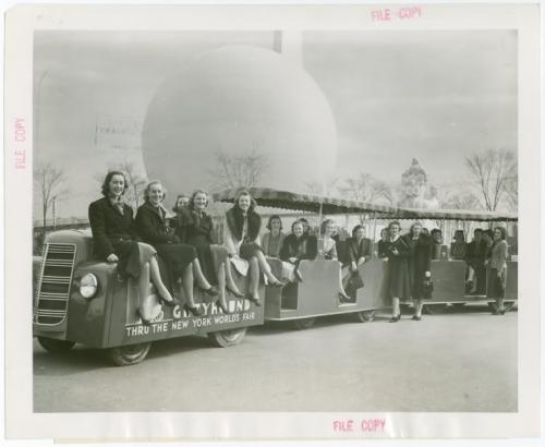
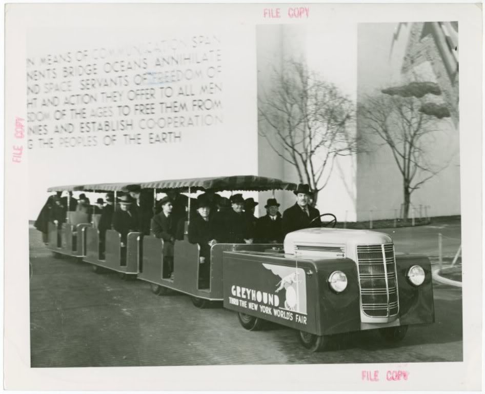
Andy After their stint at the worlds fair they were bought and taken to Wildwood, N.J. to be used on the boardwalk there, however they were converted to electric power and lost there distinctive grilles. I'm not sure but I believe the trams are still in use at the seashore in Wildwood, N.J. Ron
-
B67 questions?
39 Baby Mack replied to Bigdogtrucker's topic in Antique and Classic Mack Trucks General Discussion
I'd like to see a photo of the front of it. Ron -
The power units for the Greyhound trams used at the '39 New York Worlds Fair were built on shortened ED Mack truck chassis. Ron

-
Mack model EFU cabover
39 Baby Mack replied to Justin Seekins's topic in Antique and Classic Mack Trucks General Discussion
Congratulations She looks pretty good Good luck with her I'm kind of partial to E models myself !!! Ron -
Ben I'm surprised at you----I never thought I'd here you refer to Detroits as "Boat Anchors"!!! Ron
-
Replacing Slack Adjusters
39 Baby Mack replied to doubleclutchinweasel's topic in Air Systems and Brakes
Kent Waiting to see pictures---don't remember seeing one like that or one like Vlad sent pictures of. I'm curious?? Ron -
To our texas Marshall-RandyPP-Happy Birthday
39 Baby Mack replied to hatcity's topic in Odds and Ends
Happy Birthday, how does it feel to be that old?!!! Ron -
Thanks loads toad, no need to push it!!! Ron
-
I know you're not going to like this, and I have nothing against Detroits, but it seems sacrilegious to put one in a Mack---- then it's not a pedigreed Bulldog!!!! Ron
-
Try looking at the cab bushings---first style were threaded bushings and pins and were greaseable, in my opinion they weren't much. Second style were fiber bushings and straight pins, not much either! Last style was the best- used same rubber bushings as the last F models, these can be retrofitted to earlier trucks, but is to say the least one hell of a lot of work!!!! Try taking a pry bar and inserting it between the bumper and the cab bracket and see how much slop there is. Ron
-
Happy birthday, have a good one! Ron
-
Replacing Slack Adjusters
39 Baby Mack replied to doubleclutchinweasel's topic in Air Systems and Brakes
The older Macks had the Mack corporate brakes on them. They used these at least through 1970 as far as my experience goes and again I'm used to single axles. The Mack corporate brake used a 1/2" bolt to retain the slack adjuster along with a thick (hat shaped) washer that actually went part way into the slack adjuster. These brakes are not what you're used to! They do not have rollers in the shoes but instead use a flat wear plate. They have square brake block rather than tapered brake block which is bolted on rather than riveted on. The anchor pins are greaseable. The "S" heads on the cams are a special contour an i believe the cams are 1-1/2" 10 spline. I'm not trying to scare you, but I don't know what the parts availability would be or if they can be converted to a later style. Ron -
Thanks guys for the Birthday wishes. Ron
-
My first guess would be the "o" rings on the injectors. Ron
-
Pretty neat, old dash and interior painted later beige color!! Ron
-
I wouldn't use anything on the fire rings or the head gaskets. just make sure everything is clean, threaded holes in block for head bolts should be cleaned. Make sure you oil threads on head bolts and under bolt heads and washers---torque to proper specs. in sequence and in three different steps to final torque. Ron
-
Happy Birthday Ben!!!!
-
Happy Birthday and Good Luck with the 8V71 My birthday is very close to yours, it's on Wednesday, only problem is that's where the similarity ends---I'll be 57! Ron
-
It means you could install a dynatard (Mack engine brake)
-
the B-60 Macks were originally powered with an EN-464 overhead valve 6 cylinder gasoline engine, rated at 170 H.P. Ron
-
Timing the pump on a endt 676
39 Baby Mack replied to Lmackattack's topic in Engine and Transmission
If it's an Ambac pump a simple homemade tool will do the job, if it's a Robert Bosch it's not so easy. On an Ambac pump first things first completely blow off area on top of pump with compressed air trying to keep everything as clean as possible. You have to remove the inlet fitting and the overflow valve, these are located in the front and rear of the fuel gallery on the pump. Use a1/4'' pipe plug in one and fabricate a fitting with a valve and air quick coupler in the other. You have to remove the delivery valve out of the pump in #1---------after removing injection line for #1off the pump remove the big nut (1-1/4 socket) and long 1/2'' breaker bar. after you remove this nut there is a fitting under it which is the part you see protruding through the nut that is what the line is attached to. remove all this keeping everything as clean as possible. look down inside the pump and you will see the delivery valve and spring. Remove both the spring and using a pair of needle nose pliers carefully remove delivery valve( it will look like the old inlet valve for a carburetor only of much higher quality) Keep in mind you have to be careful to keep everything as clean as possible. Reinstall nut and fitting back into pump (without the delivery valve and spring) and torque to I believe 90 ft./lbs.( I will try to find out for sure, can't remember everything, it's been awhile!!!) Now you need to make a test line out of an old injection line--------Remove one end of an old injection line. Bend this line as necessary so that it can be installed on pump on #1 and the other end can be stuck inside of a clear glass bottle full of diesel fuel. Now apply air pressure to fitting that you made for the pump---------just crack valve open until you see a steady stream of bubbles coming from the line in the bottle. Now with the pump backed off to fully retarded position(counter clockwise) slowly turn injection pump drive hub clockwise (1-1/4" socket) while watching bubbles from the line in the bottle at the exact time the bubbles stop you have reached port closing. Torque bolts on the drive coupling to 35ft./lbs. Also when doing this have the fuel linkage in the full fuel position some say it makes a difference although I never saw where it did. You can double check your timing by rotating engine backwards past the degree marks on the dampener and then barring forward again watching bubbles in the bottle----when the bubbles stop look at the timing mark on the dampener should be within a degree of where you want it. Now remove all your test apparatus and reinstall delivery valve and spring, fuel fittings on pump, and injection line(torque injection line to 35ft./lbs. with 3/4" crowsfoot socket. Now if you have one of those big red buttons from Staples push it----- " THAT WAS EASY" That should do it, I will try to find the torque for the nut on the pump. Ron -
I see you included a shot of one of the most famous features of the B model---------the extra spacious cab!!!!!! Ron


BMT Forum Logo
