


Geoff Weeks
-
Posts
2,531 -
Joined
-
Last visited
-
Days Won
7
Content Type
Profiles
Forums
Gallery
Events
Blogs
BMT Wiki
Collections
Store
Everything posted by Geoff Weeks
-
Also resembles a Mack CRD 117, and that would not be the 1st time I have been fooled, but it doesn't look like a retro-fit, esp with that air brake bracket
-
They were made in 1 and 2 caliper brakes on a single disk. They were good, but very soon after spring brakes were mandated, and the Tru-stop was history..
-
Ooh, do I see a Tru-Stop disk E brake on the driveshaft?
-
Looks like a Timken "L" series axle. Not exactly sure which one. Double reduction axle. L240 or L245 look like what you have. I don't have a capacity, but likely far more than is allowed on the roads for a single axle, 25K? I would say it is original to the truck, right timeframe, right air brake set-up The U series Timken also looks close, but I don't think it is an exact match. Looked at my K series IHC book, and they used a U200 that looks like it could be what you have. That would be the right timeframe. Fairly sure on Timken, just not on what exact model.
-
The basic model is cast into the housing, the exact number (which contains all the things that make it fit one application) are stamp into the main housing around the area where the output shaft comes out of the box. Often the numbers are hard to read with the pitman arm in place, it blocks direct view. IIRC you had a 392, but my memory isn't all that good either.
-
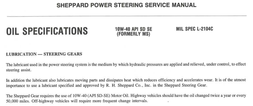
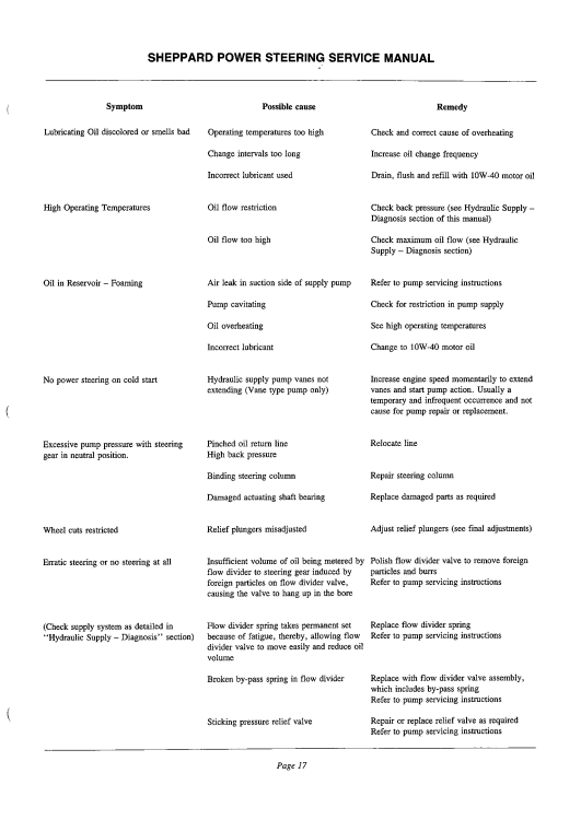
Found a screen shot of the lube requirements page. This is for the two digit and 3 digit boxes for the time period we are talking about. Later (M100) series may be different.
-
Sheppard only supplied the steering gear, the OEM would supply the res, pump line etc, so not called out in their manual for the gear. It says "wrong oil" as a problem and list the right oil, don't know what more you expect them to say. ANY oil will work after a fashion, but using what the mfg designed it for will give best results.
-
Right from the Manual
-
I have never seen a older Sheppard box that anything other than engine oil has been called for in the spec's. If you have documentation of ATF being used in Sheppard boxes, I'd like to see it. 66 would likely have the old 2 digit boxes "29, 39" etc and these were "low pressure" boxes.
-
Oil in transmission
Geoff Weeks replied to hicrop10's topic in Antique and Classic Mack Trucks General Discussion
didn't say there was, just pointing out that SAE 50 is the preferred transmission oil. In the old days, GL-1 was all they had for transmissions, Now GL-1 is almost obsolete and SAE 50 can be used in place of it with better heat tolerance, there is no down side to using it place of 80w-90 GL1 and no advantage of anykind in using GL-2 though 5 in transmissions. Most, but not all GL2-5 are "yellow metal" safe, but again, no advantage to using GL over SAE motor oil. If you look at any transmission spec sheet written in the last 40 year or so SAE 50 is the preferred, and GL-1 80w 90 as "acceptable" as long as oil temp is kept below 220 or so. Hypoid and Amboid gear sets require Gl in the higher designations, but not transmissions. H & A gearsets have a very hard wipeing action when the gears mesh, unlike spiral bevel and spur gears. EP additives are needed in these set to prevent the oil film from being wiped off the gears by the sliding action of how they mesh. EP additives have drawbacks when used where they are not needed. -
Oil in transmission
Geoff Weeks replied to hicrop10's topic in Antique and Classic Mack Trucks General Discussion
I haven't seen a HD transmission that wouldn't do well with SAE 50 oil. It is what most call for, has the aprox the same viscosity of 90 GL,none of the additives needed for hypoid gearing which is not need in transmission and can attack brass. It also handles heat better then GL Axles are a different story, there I would go with gear lube. 80w-90. -
Digging a bit more, I came up with this: But that raises a question as my IHC parts manual shows the FE970 as a Rockwell 12K axle?
-
Both are likely 9K Ok, found some info on those old axles FE970 is 12K axle I can find an FD900 which is a 9K, but not an FE900
-
Not unless you do it with the engine running!
-
Mine was a std off the shelf Vickers hyd pump. I think you should be able to find that just about anywhere..
-
There is a valve in the pump. You can see if you can free it, but I replaced the pump, it was cheaper and faster than messing around with it. Thinking more about it, I haven't seen a 3 line on a Sheppard box, but that doesn't mean it was never done.
-
Does it have a 3 line system or 2? 3 lines have 3 lines to the pump and res and 2 line has two, the box will have 2 regardless of the pump system. A flow variable pump that is stuck in low will make steering heavy. Most trucks have a suction filter inside the res itself.
-
See if this worked page0011.pdf
-
Red Dot makes sleeper A/C units that Mack used in their sleepers,
-
Anything made by man can be rebuilt or remade by man esp if he has access to a machine shop to do so! I'm betting you'll come up with a viable solution.
-
They were fairly popular with business buyers, where utility and MPG were the driving concerns. Not popular with the "macho" duelly pick-up crowd, that wanted to drive everywhere with 6 MPG. They were never "cheap" even used, they commanded some bucks at least when I was looking at them. A housing contractor I knew was looking for a truck for his son for the business vehicle, I suggested an NPR and the son had a fit, he wanted a Duelly pick-up and that is what they ended up with, but the NPR would have served the needs better and cost less to run.
-
long way to go!
-
The why, may have been someones "why not?" and then they got the answer after they built it.
-
I tried to blow up the pic and look and the coupler but couldn't see it clearly. I thought it looked like a plain coupler,but you might be right, and it has someway to transfer load (plate at bottom/top) like the jockey does.
-
??? I agree, no load on the drives. I don't think you can transfer much if any vertical load via the coupling knuckle. I've seen that company (Brant ??) that had Western Star high rail trucks, but they were much more purpose built. May be it was used to keep company drivers from "going off the rails"!😃 EDIT: may be the company name was "Brandt"?


BMT Forum Logo
