


Vmac3
-
Posts
347 -
Joined
-
Last visited
-
Days Won
2
Content Type
Profiles
Forums
Gallery
Events
Blogs
BMT Wiki
Collections
Store
Everything posted by Vmac3
-
I attend the truck show every year at the international center by the airport.
-
Something else to consider. Check the shaft that the spinner filter spins on. Sometimes over time the shaft wears out and the filter will not spin true and will wobble a bit and give you that hum. V
-
I totally agree. I don't want to get philosophical, but it's better to help someone up than to kick them while they are down. If we all can learn from each other then it's a win win for everyone. Imagine given a bucket of bolts and a box of gear to put back together and not having any clue how and not knowing what the specs are? If the original poster of this thread were to do that then geez, imagine the catastrophe? Anyway I'm glad for your contributions and JoJos. V
-
@ JoJo Its okay, I am not here to judge, just here to help in any way I can and learn from smart people as yourself.
-
No problem. That was a lot of work you did on that truck.
-
Before you do anything make sure the cam damper and gear is off and the rocker shaft is off. Set the camshaft to TDC. You will see the TDC mark on the cam, line it up with the hash marks on the #7 bearing cap. The crankshaft has 2 dots that face the 12 o'clock position and the double idler gear has 1 dot that sits between the 2 two dots of the crank at the 6 o'clock position. Once you have done that then adjustable idler gear goes on. Once you have done that put the cam gear on and verify that it is at TDC. This part is very critical otherwise the engine is going fail real fast. Make sure you set the gear backlash to .004" between the adjustable idler and the camshaft gear. Once that is set verify thast it is still at TDC. If it is then you are good to go. Put the flywheel housing on. Follow the PDF that I attached and your good to go. V Timing Gear Replacement. MP7.pdf
-
Here you go. Take your time and follow the service bulletins. Make sure you adjust the gear backlash properly, otherwise you will have a bigger problem other than a bucket of nuts and bolts in front of you. V Ting Gear Plate Reseal.pdf
-
These were the vmac2 vehicles 1996-97. Partial authority fuel systems. Really good engines.
-
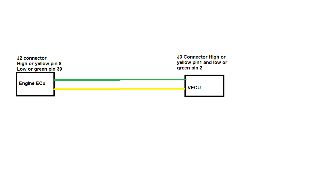
Check all the fuses for the engine and vehicle ecu first, an offline vmac module will set this code. The 6-4 code you are referring too is the J1939. This is used for communication between the engine ecu and the vehicle ecu (both vmac3 modules). The other modules plug into the backbone of the J1939 (auto trans, abs, and any other module). The vmac3 system did not have any external terminating resistors. They were built into the vecu and the engine ecu. To check the datalink, find the datalink connector, its under the dash on the driver side, beside the steering shaft. Disconnect the batteries, with your multimeter set to resistance, probe pins C and D. You should get 60 ohms. if its at 110 or 120 then you have an open circuit. The terminating resistors have a value of 120 ohms each. When they are connected in parallel the resistance goes to 60 ohms. Let us know what you find. V

-
Simple shifter knob change.
-
Hey Jojo your turn.
-
I am glad I can share my experiences. Vmac2 was a fantastic model. The best by far. They did have some issues, but the time 1997 came around they sorted most of the bugs out. If we look at the contrasting differences from 1997 to today's vehicles, you cant dispute the fact that today's vehicles are safer and more comfy to drive. The EPA drives the industry for change. Some would argue for the worse others would argue for the better. The big deal is if someone is to get into a 2021 vehicle and treat it as if was a 1985 truck, they will surely be disappointed. Another big issue is training today's techs. Anyway I hope everyone here has a safe and happy Christmas holiday. All the best in the new year. Stay safe. V
-
Okay here it goes..... In the early 90s Mack released its first version of their electronics called VMAC (Vehicle Management and Control). The first generation was called VMAC1. The fuel system was a partial authority system where it had 2 modules. 1 module was called the FIC (fuel Injection control module) and the other was the vmac module. Each module had their own functions, the fic controlled fueling to the pump and the vmac module controlled vehicle electronics. They both communicated via j1587 datalines. Both modules where located on the passenger side kick panel. The injection pump as JoJo mentioned was built by Robert Bosch. The FIC sent commands to the pump for fueling. There were a couple of electronic components, a rack actuator, rack position sensor and a timing event marker sensor. As JoJo mentioned the pins on the pump would get loose and had to be replaced. In the front on the pump was the timing mechanism, Mack called it the econovance. This was controlled by a actuator that allowed for oil pressure to actuate the econovance. This worked by two helical gears that would allow for advance and retarded timing. This engine was a breakthrough for Mack because now you can have specific customer data programming, better fueling and fault diagnostics. Vmac2 was the same where it was still a partial authority fuel system but with the use of 1 module. This allowed more programming features. In my opinion this was the best Mack engine ever built, 2 million was no problem for this little 12litre engine. These engine produced more hp than what was advertised. I have dynoed several of these and they produced 20% more than what was advertised. These push rod engines had two peice pistons, that were full floating. The engine brakes were nothing to write home too. They used Jacob's engine brake and an exhaust brake that Mack called a stealth brake. It was an air actuated exhaust brake that sounded like the engine was being muffled. Lifters were a flat tapped. The new emissions standard came out in 1998 (I believe) which called for a reduction NOx and particulates. Mack introduced Vmac3, it was still an E7 engine but the engine block was reworked to allow for a new fuel system redesign. Mack used Robert Bosch components to make up their fuel system. They used the infamous EUP (Electronic Unit Pump) system, it is still considered to be a pump line nozzle system but each cylinder had their own individual pump that was mounted in the engine. So any cylinder to cylinder variation can be corrected at anytime, where as the partial authority it cannot. These pumps were driven by the engine camshaft, so you can imagine how heavy this cam would be. The injectors were pretty much the same, they sat in the cylinder head in between the valves. So you may ask why did they come up with this fuel system? Well the reason is the partial authority pumps were only able to produce around 20 thousand psi of injection pressures. The eup fuel system brought it closer to 30 thousand. This is a big deal for deisel engines because when diesel fuel is injected, it is injected as a mist and not vapor. So the smaller the fuel droplet the less time is needed to compress the fuel to reach its injection pressure, inject it, heat it, turn it into a vapor and oxidize the fuel in which combustion occurs. Getting away from the science, the engine itself was the same, it was still a 12litre with a lacklustre engine brake. It was still a push rod engine with the same piston design, except the bowl of the piston was a little different. Lifters were steel rollers, then they switched to ceramic rollers with spring loaded push rods. No egr yet. The electronics gave way to a full authority fuel system, the engine ecu was mounted on the right side under the eups and under a heat shield. Later on they moved it to the left side mounted on the intake. Mack called this engine LSR (Left side redesign). Vmac3 had two modules the engine ecu and the vehicle ecu. The vehicle ecu was mounted on the passenger side kick panel. They both communicated via the datalinks, j1587/1708 and j1939. These are a set of languages and physical characteristics of the modules. JoJo mentioned the issues with valve trains and engine brakes with several updates they released. In 2002 mack introduced the CCRS engine Contantly Controlled Rate Shaping System). The fuel system was anle to produce a pilot injection before main injection. This allowed for lower particulates and NOx emissions. This is why these engines have a different camshaft compared to its earlier version. Mack started to loose their fame as a built proof engine, but what customers didn't realize that the grass was not greener on the other side. Most manufactures started to transition to egr/vgt engines. By late 2003 the end came for the non egr engine. The EPA mandated for further reductions in emissions for 2004 model year. This time they especially targeted NOx, and there you have it the egr was installed on the E7 Etech engine. ASET AC and ASET IEGR engines were introduced late 2003. The engine was still the same e7 12 litre engine. But now they changed the camshaft, piston bowl design, turbocharger, more electronics egr system and a better engine brake. Well at least some good came out of this with their engine brakes. Really strong and enough to put you tight agianst the seat belt. The iegr engine did not have all the mumbo jumbo compared to the external egr. The iegr was fitted into offroad/construction vehicles, simply for space. The iegr used an extra bump on the exhaust lobe to push exhaust gases into the intake during the intake stroke, so the exhaust valve would open during the intake stroke. This is not new technology, Honda used this in some of their cars. Anyway the issue with these engines are they always had exhaust gasses being dumped in the cylinder and this caused a lot of grief in the beginning. Sludging of engine oil, worn rocker shafts worn pistons and liners and blow by. So Mack introduced software updates to change the fueling. Anyway no need to discuss about the external egr engine. I'm sure everyone knows about this abortion of an engine. The engine itself was good, it's just what was attached to it caused all the grief. Sorry for the long winded post but I was walking down memory lane on this one. These engine taught me so much and it taught me how much I really did not appreciate the original Etech engine. Looking back the Etech was an excellent engine. I'm sure I missed out on a lot of things here but thanks for allowing me to share. V
- 40 replies
-
- 12
-

-

-
There are plenty debates on reusing engine components, pistons, rods and the likes. Its all about how much money you want to spend. If the pistons are not out of round, ring lands are good, no cracks and the thrust and ani-thrust sides show little to no wear, then it can be reused. Connecting rods can be checked by using a dial indicator and rotating the engine and measuring the heights of the pistons. The liners need to be secured to the engine block bolted down with large washers. Anyway if you plan on keeping the truck for a long time then it will be a good investment to have all pistons replaced. But its up to the individual. V
-
I remember that the older Mack trannys were pressed on with the yoke where they were inside the bearing cover. Can't really say I remember. Its been a long time now.
-
Whats that old saying? There is never enough time to do the job right the first time but there is always enough time to do it twice.
-
Good point. If the tranny yoke is loose then the tone ring will slip.
-
There is no screwing around at this point. I hope your tech has enough experience, because this can go sideways in a real hurry. Don't rush the job, make sure the job is done with cleanliness in mind. Also don't forget to check the rod and main bearings, because coolant contaminated the crankcase. The rods and main journals need to be checked for pitting and excessive wear. Don't have the tech replace anything until the rods and mains have been measured. After the liners are pulled, block deck cleaned and the block deck is checked for straightness, make sure there are no pits in the counter bore. Any erosion on the counter bore will need to be cut. I measure the counter bore with a depth micrometre and measure in 4 different spots to check the condition of the counter bore. If the counter bore is to be cut, make sure the counter bore cutter has a good cutting bit otherwise the shelf of the counter bore will have waves and it will eventually leak when put back into service. There is no need to rush this. If you take too much off at once you will ruin the shelf. I can't explain how critical this procedure is. Max depth is 4.040". If you have some pitting that can"t be removed, according to Mack it is acceptable as long as there is no direct path to the crankcase. Man oh man have I seen a lot of crappy in-frames where care was not taken. Don't use gobs of silicone. About a 3-4mm bead is all that is needed. The largest shim is installed followed by the thinner. Try and have your tech cut the counter-bore as little as possible but making sure the shelf is in good shape. You want the height of the sleeves as close as possible, this will ensure a good seal of the fire rings. Have some paper towel in the bore, to catch the filings when the counter bore is being cut. After cutting the counter bore remeasure it using a micrometre. Make sure everything is spotless. Max sleeve height is .029". Try and get the liner height to the upper end of the spec. When the heads go on you can bet the liners will go down another .001-.002". If the tech is on the low side, then, well, it all goes to sh#t. This is a job where extreme care needs to be taken, a lot of experience on the tech is needed. There are so many things that I did not point out, its in your techs hands. Like I said there is no screwing around. V
-
Yup, I agree with Jojo. I would not take the chance. With EGR engines the engine oil is very abrasive because of soot loading. Lots of good aftermarket parts out there. Just be sure your tech keeps everything clean when assembling the engine and the tolerances are checked. You should be good to go.
-
The code is saying that the current is low and or open circuit. The speed sensor circuit has 2 dedicated wire that are twisted together. Since its a series circuit, any added resistance to the circuit would decrease the amount of current flowing through the circuit. With the key off, disconnect the J2 plug at the VECU. Disconnect the speed sensor and jump the two terminals at the sensor with a wire. Measure the resistance at the J2 plug at pins 11 and 12. The resistance should be very low with continuity. With one lead on pin 11, check to see if any other pins with the other lead is shorting with pin 11. Do the same with pin 12. Should take only a few minutes. If that is okay then there is a square connector on top of the transmission that would get loose. Give that a shake and see if the resistance value changes. If it does, open the connector and check the pins. If they are okay put a zip tie around the two halves of the connector and secure nice and tight. Let us know what you find. There are a lot of smart people here that can chime in. V
-
Sorry, I should of asked earlier. What model trucks are they?
-
By pass the coolant lines at the Davco and drain the Davco filter housing in a bucket. If you not sure there is a valve on the bottom. Drain it until clear fuel comes out. Don't drain it completely. Drain 250ml (sorry for the units of measurement I'm Canadian). Run the truck and recheck it. You may have to do this several times depending how much coolant contamination there is. As for the EUP codes hopefully they will clear up. Finger crossed. Let us know what you find.
-
JoJo are you talking about one of those Rig Masters that sit on the back of the truck and has a small Perkins diesel or one of those espar heaters? You would be correct. I think it's possible, because coolant and fuel do meet through a heat exchanger. If the heat exchanger is cracked then absolutely. Up in the northern states and into Canada those Davcos or Raycors are fitted with coolant supply lines. The plastic ring that secures the filter assembly was always chewed because techs did not have the proper davco wrench.
-
Yes it is. No external difference. May want to check if the driveline is compatible. Software in the modules need to be updated.
-
The first Volvo engine that Mack recievd was the MP7. It was a US04' emissions engine. Never saw or heard of a MP8 04 emissions. US07 was the introduction of exhaust aftertreatment. I would be wary of this deal.
BMT Forum Logo
