


oldspwr
-
Posts
152 -
Joined
-
Last visited
-
Days Won
7
Content Type
Profiles
Forums
Gallery
Events
Blogs
BMT Wiki
Collections
Store
Everything posted by oldspwr
-
While the parts were out getting powder coated, I decided to work on the oil pump. I started with cleaning the heavy stuff out the outside of it first... Then I decided to take it apart to clean the inside as well... I also had a conversation with Stan A regarding the oil pump and he recommended removing and cleaning the pressure relief valve as well... When I was done cleaning everything I reassembled the pump and gave it a coat of Cummins beige. I found the gasket on eBay fairly cheap also... More to follow...
-
Thanks for the comments... mrsmackpaul... I was able to find a better pitman arm so I didn't look in to just replacing the ball. I have always used painters tape for my fab work. Not just regular masking tape, either yellow or green 3M painters tape. If comes off fairly easy, even after a few days, and generally doesn't leave and adhesive behind. And then I use a ball point pen with that...
-
When I first started this conversion I ‘thought’ I had all the pieces and parts I needed... Well I was wrong! But fortunately, thanks to my all Brockway friends, I was able to get everything I needed... The first issue I realized I had was not having the correct pump. I had asked this question in a separate post... My original oil pump did not have the provisions to mount the power steering pump. Fortunately Dave M was reading this post and called me to let me know he had the oil pump I needed. So several weeks before the Holiday I spent a Saturday visiting friends in NY. First I stopped at Dave M’s in Delhi, checked out his great collection and picked up this oil pump. Ironically Dave also helped me out with the power steering pump for the 671 in my Dad’s 361. g[/IMG] The second problem I ran into was not having the correct steering arm for the 18k Rockwell axle we installed a few years back. The front axle did not come with a steering arm so Russ used one from a 12k axle. Although it fit, it did not fit well and had a little slop in it. I also knew it was important to get the right steering arm to maintain the correct steering geometry (ie Ackermann steering geometry). Brian Enck mentioned he had a parts truck with an 18k axle that originally had power steering. So after finishing up visiting with Dave I went to Brian Enck’s in Otego. Equipped with some heavy duty tools and a set of torches, we proceeded to remove the steering arm from the front axle. Brian wears his hood up to protect his identity... I also had an issue with the pitman arms I had collected over the years. Once was too short... And the other had a ball that looked like it never saw a drop of grease in its life... Brian also had an extra pitman arm for me so I was able to come home with this... G] Last but not least I stopped at Paul Polizzi’s on my way home. I was able to check out his new V12 cabover with the custom dual stacks... That’s it for now!
-
The annual Brockway show is coming up in a few weeks...
-
Another item I had to tackle was the location of the coolant filter. On this truck it was mounted to the top of the air intake with a re-purposed bracket (I don’t think it was originally a Cummins piece...) So I decided to modify the original bracket and weld it to a piece of flat stock. Then I could bolt this behind the reservoir bracket using the bolts that hold the reservoir on (if that makes any sense...) A future picture will help clear this up... Once I was done with all the brackets I decided to sandblast everything, starting with the reservoir... And here is what I wound up with when all the blasting was done... This takes us up to the week before Christmas. Right after I finished sandblasting the parts I dropped them off to get powder coated. As I mentioned before, there is a guy who does this locally who is reasonably priced and turns things around quickly. That’s it for now...
-
Since the intake is aluminum, I decided to use 3/8x16 studs instead of bolts. When the mounting bracket was done I started working on the reservoir... Several coats of paint had it fairly well protected but there was some rust under the brackets... One thing I noticed is that the lid must have been leaking around the expansion fill plug. The used silicone on the top to try to seal it and some type of clear epoxy on the bottom... I wound up bead blasting the lid in the cabinet and then had a friend weld a bead around the bottom of the lid. Hopefully this will prevent any future leaks. One thing I did notice was that the lid on our 761 had a vent in it. This one didn’t and neither did the chrome one on my Dad’s 361... More to follow...
-
The Cummins was drilled and tapped for 9/16” x 18 bolts. I had a hard time holding the bracket in place and trying to start the bolts so I wound up making (2) 9/16” studs that were about 1 1/2" long. I screwed these into the block and it made life a lot easier setting the bracket in place. So here is my first test fit... Once I was happy with the fit, I moved onto the piece that bolts off of the top of the air intake. For this I used a piece of 3/16” plate but wound up making it longer than the original piece. I decided to tie it into all (3) bolts on the intake instead of only (2)... Once that piece was done I decided to drill all the reservoir mounting holes in the 10” wide plate. I also drilled some 1/4" holes on the side of the plate so that I could use some line cushion clamps for the fuel shut off wire along with the Jake throttle switch wires... Then I moved onto the top angles for the bracket. I cut a total of (3) of these... And then welded them in place... I also radiused all the edges of the plate... And here was my last trial fit but this time with the top support bracket set in place... That’s it for now...
-
When we last left off I had just finished bolting some of the painted pieces on. One of the other big items I needed to tackle was the mounting bracket for the power steering reservoir. Since this truck has a new chrome Lubri-Finer on it, I decided to mount the reservoir under the hood, directly off the block just like our 761. So I took a hard look at our 761 and took some measurements and dimensions of the factory bracket. I also sketched up the piping diagram... At first I wasn’t sure if our 761 had the correct factory bracket on it since it was definitely repaired a few times. But after talking to Richie, he confirmed it was exactly what the factory used. He also mentioned they were built a little too light and were often repaired. So at that point I decided to make mine one step heavier. I stopped at the local steel place and picked up all the pieces I needed, including some 2” angle, 10” wide flat stock and some 2” flat stock. But this time I used 3/16” instead of 1/8”... I had bought a press brake a while back and never had a good opportunity to use it. So I decided to try it to bend the 10” 3/16” plate steel I bought. It actually worked pretty well... Once I had cut the angle and bent the 10” plate, I cut and filed the bottom angles to fit... And then welded them into place... More to follow...
-
Thanks for everyone's comments... Hayseed... I realize it appears that I cut the frame just to remove the original steering box, but in reality I duplicated how Brockway installed the power steering box from the factory. They cut the frame rail, added the large piece of C channel over it and then added another L piece over the C channel. On the bottom of the pic below is the factory piece of frame rail from a 1976 N761T Brockway that had power steering (essentially the 300 and 700 series were the same...) In fact you can still see some of the factory part numbers stenciled on it. So you are right, I could have removed the radiator and jacked the engine to remove the factory box, but I had to cut the frame rail anyway in order to duplicate what the factory Brockway power steering frame rail would have looked like. With this type of design, with the large C channel in place, it was very difficult to change the steering box without removing the radiator, especially in other models (like 358,359,361, etc...) Stan A, who worked for Brockway, said they issued a factory procedure on how to replace the steering box. Instead of removing the radiator, they said to cut the C channel, lift the box straight up and out, and then weld the cut piece back in after the box was reinstalled. Again in the pic below, you can see that the top piece was an original C channel that someone cut to remove the box but never welded the piece back in. This piece was a little tired for my use so I decided to make a new one.
-
One I was done painting the parts I moved back to the frame. I decided to fill the holes for the Ross box. Using a 5/8” piece of rod, I cut pieces to fill each hole and welded them in place. Once they were welded in I ground the surface flush and then cleaned up with section I was working on... Then I gave it a quick coat of self etching primer... And finished off with some yellow Rustoleum I had. You really won’t see this section of frame anymore so any color would work, but I had some yellow left over from a street sweeper I rebuilt a few years back to clean the fairground for our ATCA truck show... About a week later, I set the steering box in place using the cherry picker. I may have mentioned this before, but I took a 3/8” NPT pipe plug, drilled the center out and put an eyebolt through it. This is what I used to pick the box up and its perfectly balanced from this spot. I some cardboard and towels down on the frame as well... At that point I gathered up the parts I had painted yellow a while back. The paint Russ gave me was enamel which was left over from when we painted the 18k front axle. It works pretty well but yellow is a tough color to paint. It seems like you need a number of coats to cover everything well. Otherwise it seems like you can see right through it in spots. Then I started bolting things together and this is about as far as I got! That’s it for now...
-
The original bumper brackets also had 5/8” thick spacers behind them. My suspicion is that the front bumper came off of a 758 or 760 since the square holes in the bumper are slightly further apart than the 358 or 360 bumpers. I know on my Dad’s 361 we used a 761 bumper and wound up using 761 bumper mounts as well. So with the addition of 1/4" steel plate, I wound up make a new spacer out of 3/8” steel plate... Once I was done making the spacers, etc, I gathered up all the pieces that needed to be painted... I sandblasted them and then shot them outside with some extra Paint that Russ had given me. This is a busy pic but you get the idea... That’s it for now!
-
Thanks for everyone's comments!!! Paul, I know it is unusual to cut the frame, but I am duplicating exactly how Brockway would have installed the power steering. I had a section of frame rail from a 760 that I used for reference. At that point I decided set the C channel in place one more time. I also had a cracked Sheppard 592 box in my collection so I gutted it to help reduce the weight and bolted that in place as well. The box alone weighs 200lbs so it was much more manageable empty. Now that the C channel was done I need to work on a few small items. The first item was a space for the fender bracket. The original fender bracket had (2) 1/4" spacers behind it. With the addition of the new C channel plus the half angle piece that bolts to the top, I need to make a 1/4" spacer that fit under the bottom half of the fender bracket... Once that was done I moved onto the bumper bracket. For some reason, this bracket was much taller that the other ones I have seen and it would wind up hitting the upper half angle piece. Here is the bracket compared to a spare I have... So I wound up trimming about an inch off of that piece... More to follow...
-
When I last left off I had just finished cutting the notch out of the frame. When I was finished with that I trial fit the new C channel piece I made... Using the C channel as a guide I marked the new holes for the Sheppard box. At that point I realized I needed to drill (8) new 5/8 holes. I actually drill them to 21/32” which is the same size hole the factory used. I tried to rent a magnetic drill to make life easier but it wasn’t available so I used my trusty 1/2" 18V cordless Dewalt. Once the holes were drilled I decided to make the spacers that needed to be welded to the top side of the C channel piece. Since my frame is 3/8” thick, I needed to turn (2) spaces of that thickness. These are used to keep the steering box flush against the frame after the original section is cut out. I started with the piece I had left over from making the throwout bearing spacer for the Cummins conversion in the 155W... I started by turning the outside down to the right diameter but then used the mill to drill the center whole. My tail stock needs to be centered on my lathe so that’s why I used the mill... Once they were done I welded them to the C channel... More to follow...
-
I have the camper parked in front of the 360 so it’s pretty tight quarters, so some of my pics will be a little close... I had my Brother stop over and he was able to help me remove the fender and set it off to the side. At that point I started removing all the other brackets, etc... Once everything was removed I dug out the front section of a 760 frame rail I had. This is from the front end we bought for my Dad’s 361 when we converted it to power steering. I made another cardboard pattern and transferred it to the 360’s rail... I wasn’t able to remove the manual Ross steering box due to the length of the shaft. So I left it in place while I was cutting. Once I made my first cut using the cutoff wheel, I was able to pull to the box out. I also realized this truck has a 3/8” thick frame as well... After a little more trimming, cutting and filing I wound up with this... That’s it for now!
-
I also drilled the bottom holes with the mill also and this worked out fairly well... I waited until all the holes were drill before I cut the curved section out of the top since I knew the curve would make it harder to keep level on the mill table. I transferred the shape from the existing piece onto a piece of cardboard and then traced it on the new piece... And when all was said and done this is what I wound up with... More to follow...
-
To begin I dug out all of the parts I had collected for the upgrade, including the large C channel that is need to go over the frame... This part had the section cut out of it to remove the steering box (the factory Brockway service procedure). I misplaced the section that came out but it still wouldn’t we be a hard piece to duplicate and weld in. But for some reason the bottom of the C channel was extremely rusty and paper thin. I thought about cutting it out and replacing it but then decided it would take the same amount of time to make a new one. By chance I wound up talking to a local fabrication shop a few months ago and they bent some 1/4" plate for a hitch I made for my Dad’s 361 (more on that at a later time...) So I had them bend a new piece of 1/4" plate for me... At that point I started transferring all of the holes, etc to the new piece... I started cutting the large hole with the cutoff wheel but finished it with a jig. In my experience I never had much using bimetal hole saws for the larger holes so this worked ok for me... Once the larger hole was done I moved onto drilling the holes. I removed the vice from the mill and clamped the new piece to the table... More to follow...
-
Looks like the Brockway Message Board will be down for a while so I figured I would share a post here... A few years ago I was able to buy this 1968 N360T Brockway from a good friend of mine, Russ Bachman. My intent is to keep the truck as original as possible, but one improvement that I am going to make is the addition of power steering. The truck is a bear to steer, especially when I am trying to shuttle it in my driveway and get in parked in the garage. A few years ago I bought a complete power steering set up from Richie Z. that was set up for a Cummins. It included the 592 Sheppard box, frame brackets, supports, reservoir and Vickers V20F pump with the coupler. I used the box on another project but was able to get a another one from Stan A. I dug all the parts out last week and realized my first challenge was the mounting of the power steering pump. The truck originally had an NH250 but was replaced with a NHCT270 out of a single axle Huskidrive 361. Russ stopped by over this past weekend and mentioned that the 270 originally had a belt drive power steering pump. I took a look at the motor and realized there are no provisions for the power steering pump on the back of the oil pump... So my question is what do I need to change to be able to use the gear driven Vickers pump? I believe it will be similar to this pic of a 350 Big Cam I have... On a side note, the OEM Cummins tag is missing. It was replaced by a tag from 'Cummins Metro Inc. New York and New Jersey' when it was rebuilt. More to follow...
-
After market intake manifold?
oldspwr replied to Dusty Vic's topic in Antique and Classic Mack Trucks General Discussion
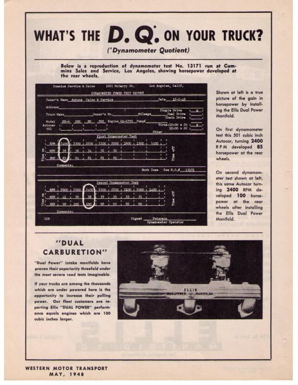
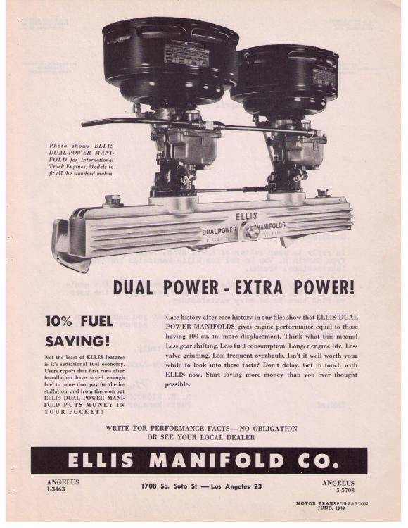
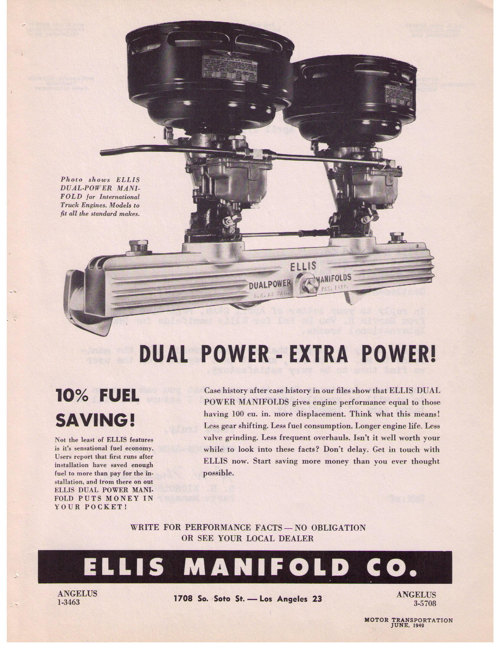
Actually the advertisements noted 10% more fuel economy and more power.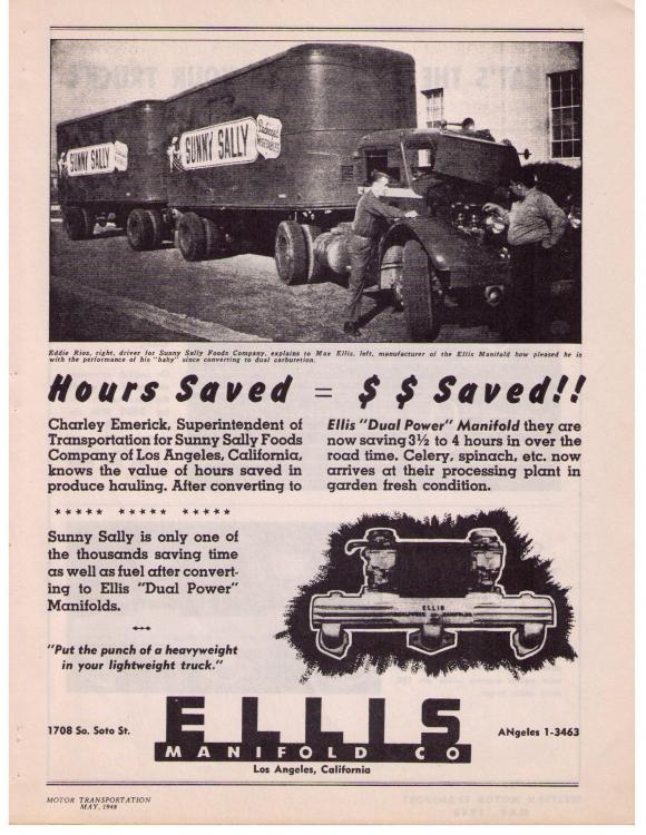
-
After market intake manifold?
oldspwr replied to Dusty Vic's topic in Antique and Classic Mack Trucks General Discussion
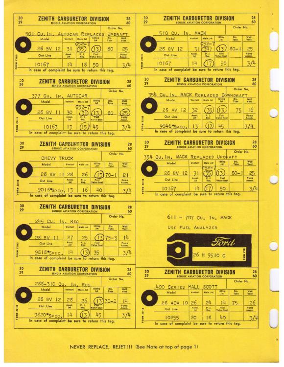
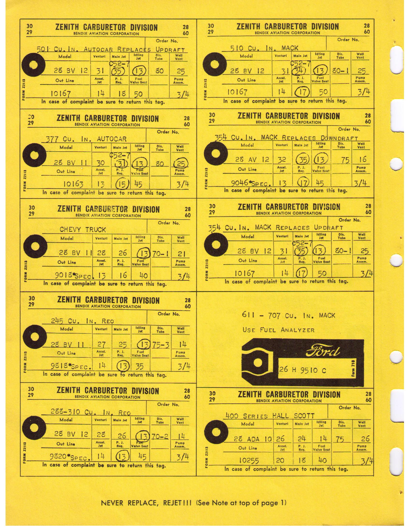
Below are some more pics, specifically in reference to the 510....thumb.jpg.27a3724db513ab7c40629c63111a7669.jpg)
.thumb.jpg.11dd615475e6ee96ed97c61ee7aa8327.jpg)
-
After market intake manifold?
oldspwr replied to Dusty Vic's topic in Antique and Classic Mack Trucks General Discussion
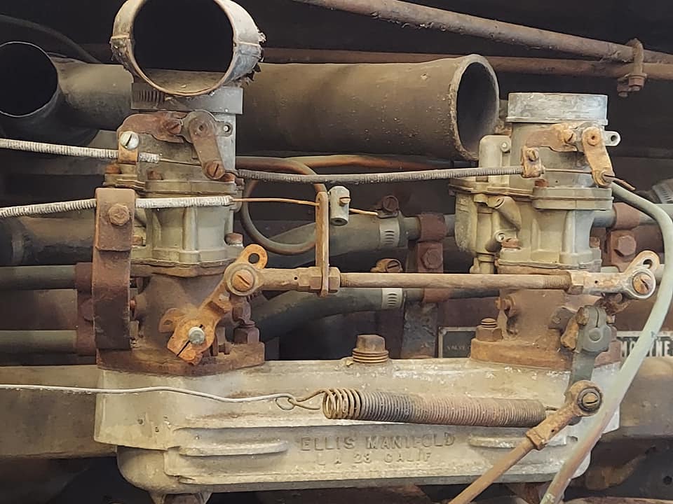
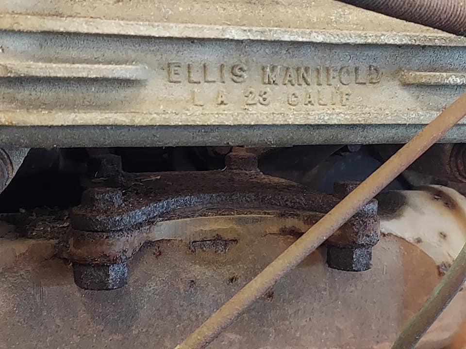
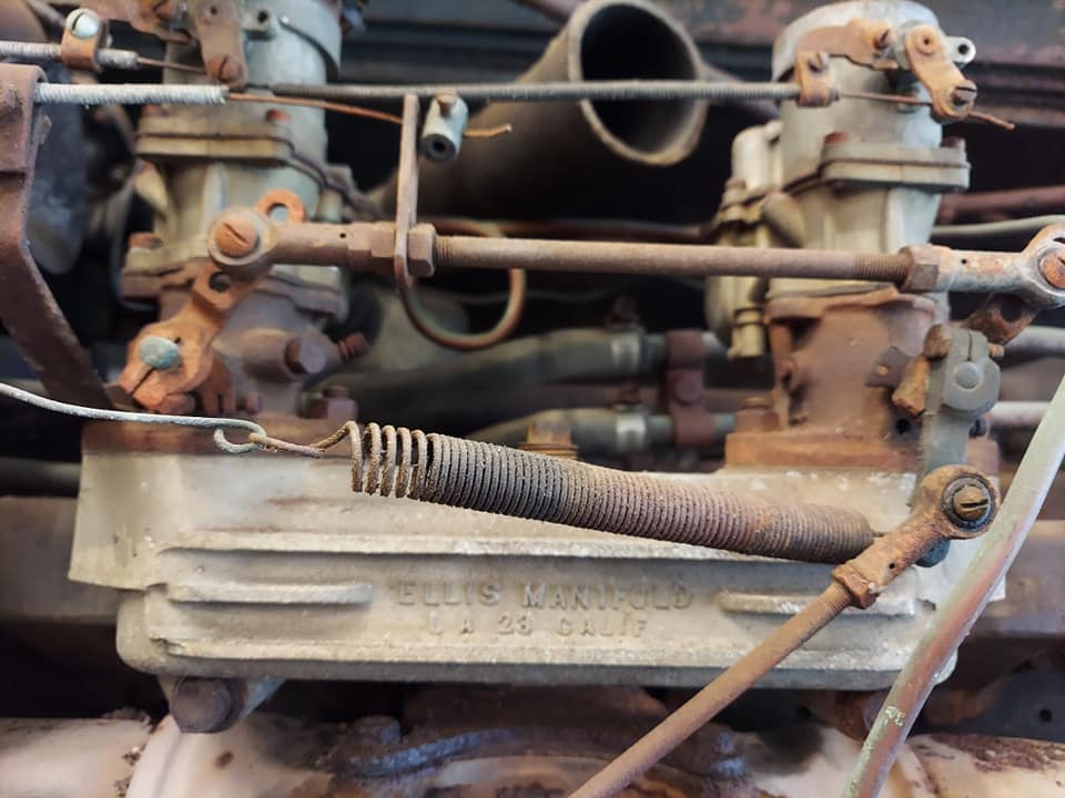
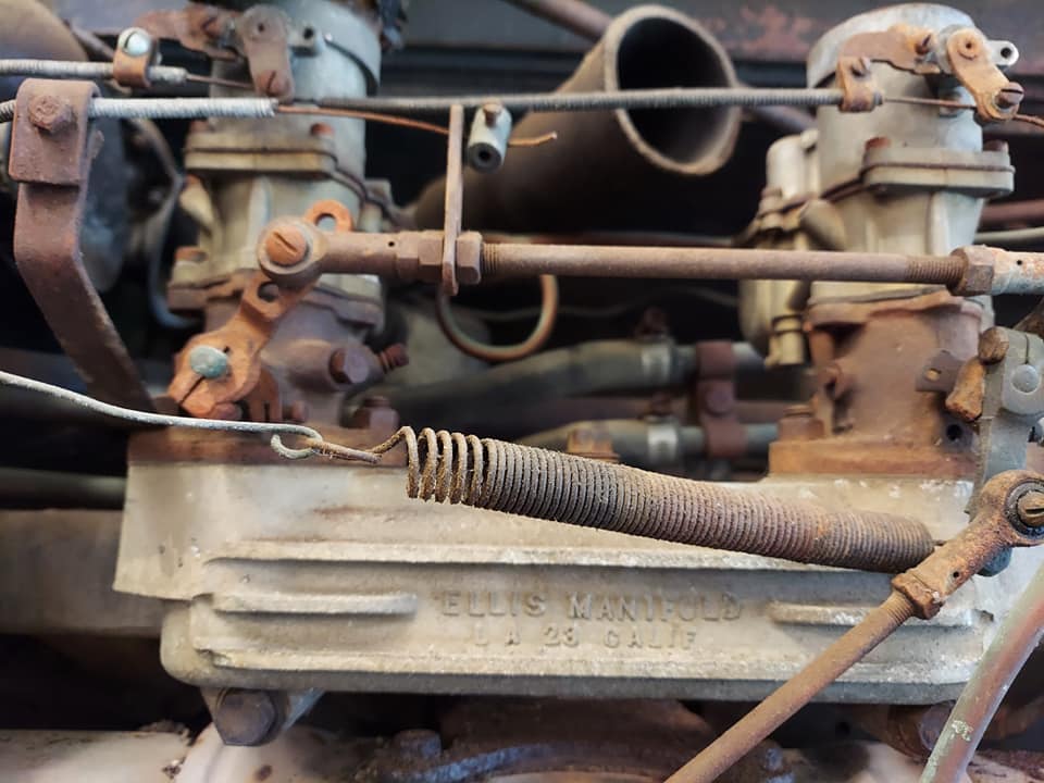
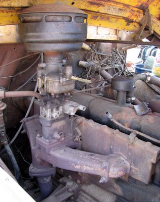
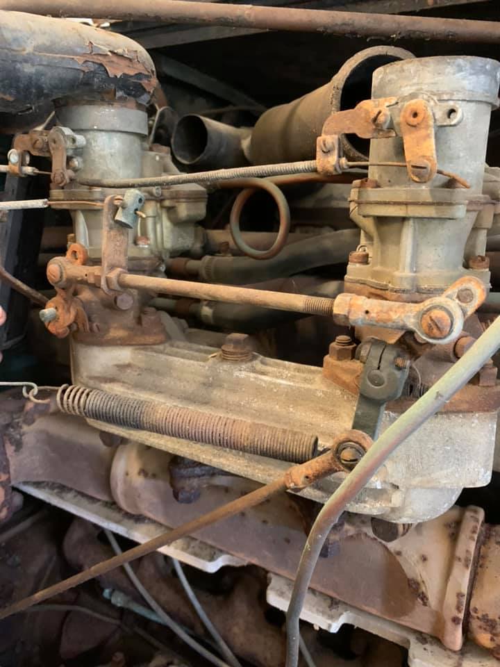
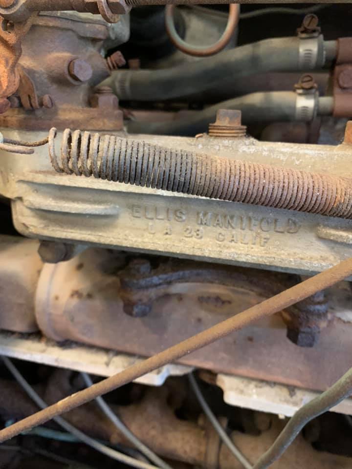
Acutally i just realized you have a different truck than the one on FB... Here are some pics of that Ellis setup...

-
After market intake manifold?
oldspwr replied to Dusty Vic's topic in Antique and Classic Mack Trucks General Discussion
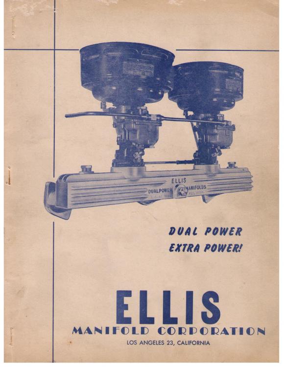
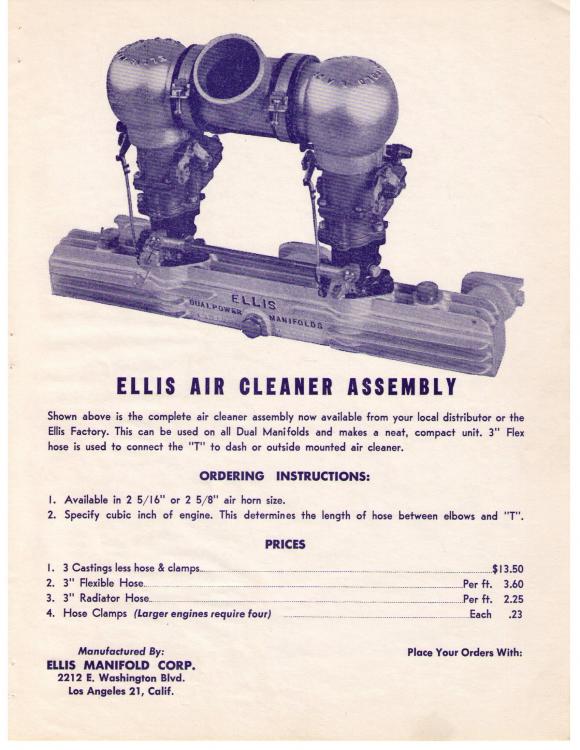
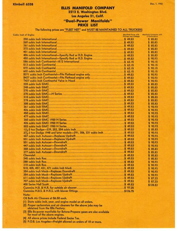
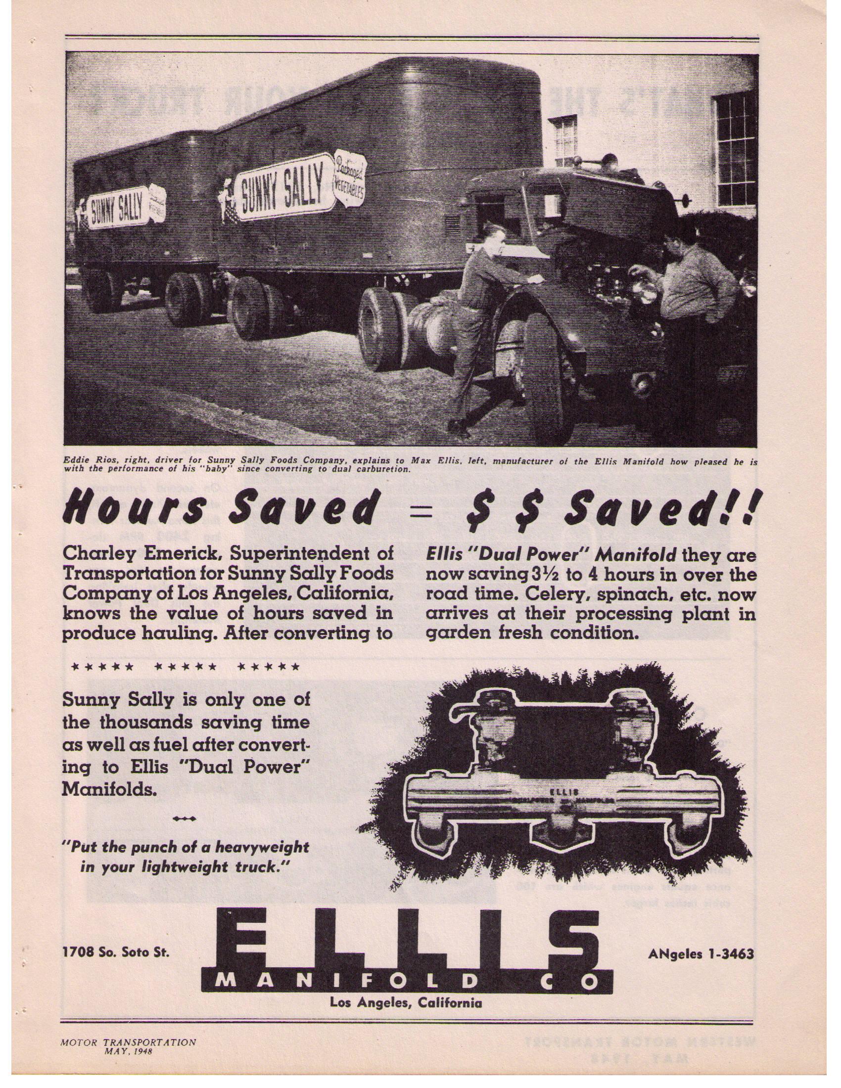
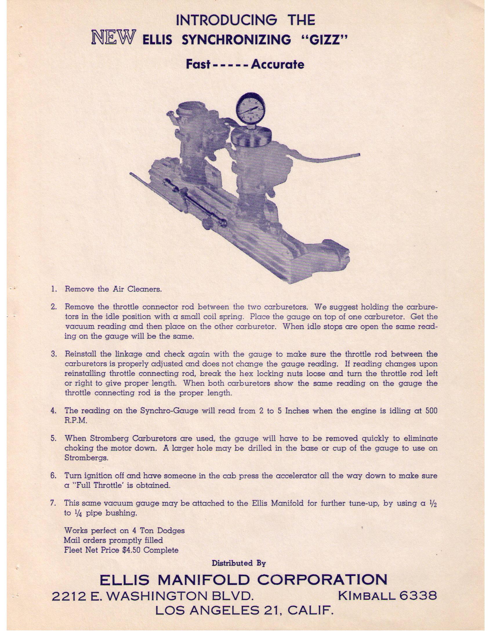
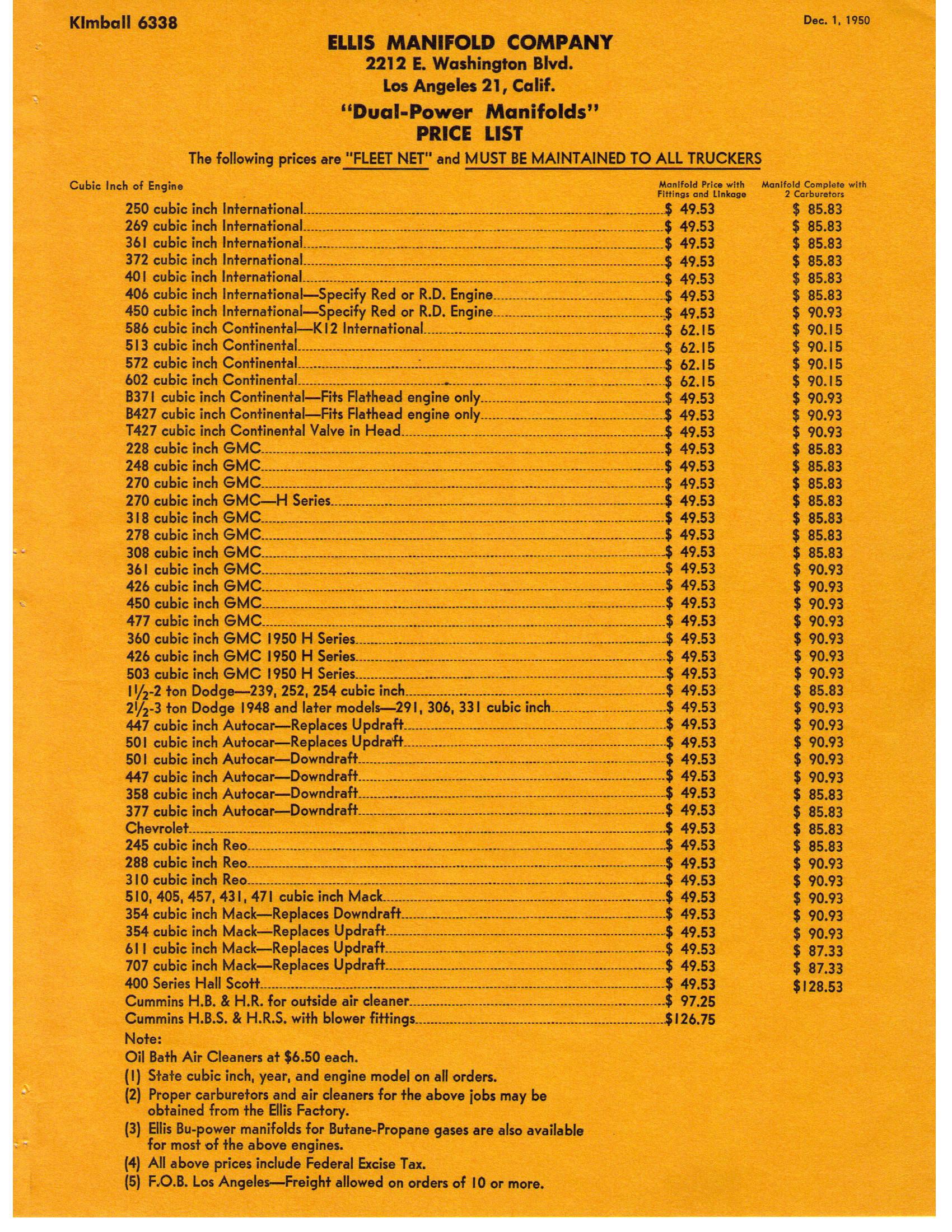
I have a 'thing' for Ellis manifolds and was happy to see the pics you shared on FB. Max Ellis started the company near Los Angeles and primarily made intakes for larger trucks. He started with Butane power manifolds, moved on to dual carb manifolds and even made exhaust manifolds for some gas motors and even Cummins. On a side note, I am working on installing an Ellis on a 572 Continental in my 46 Brockway. My Dad talked about these manifolds years ago and ever since I have been collecting pics and literature. Here are several pics of some literature...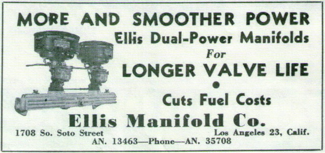


-
Anyone recognize this motor
oldspwr replied to Big R's topic in Antique and Classic Mack Trucks General Discussion
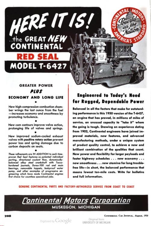
For reference, here are 2 other pics of Reo Gold Commets along with an advertisement for an overhead valve Continental...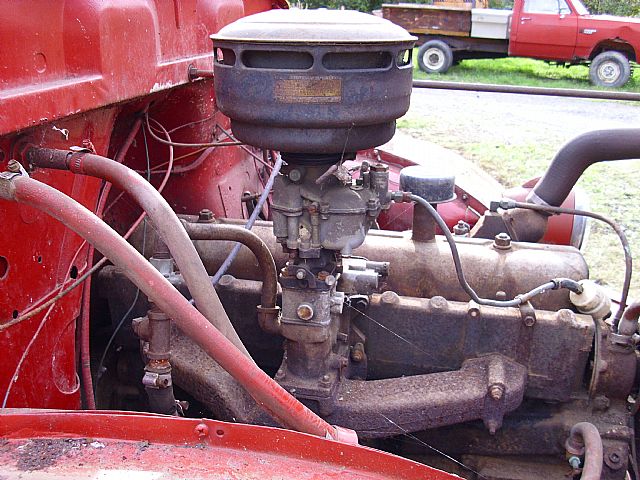
-
OEM R model turbo boost gauge?
oldspwr replied to seyser's topic in Antique and Classic Mack Trucks General Discussion
I have this gauge in my collection, I re-purposing it for a 761 Brockway... Tom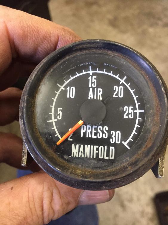
-
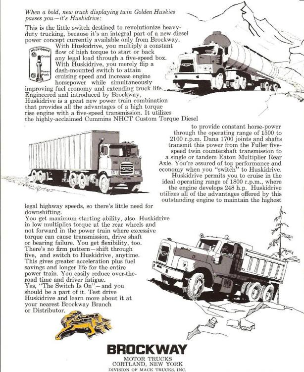
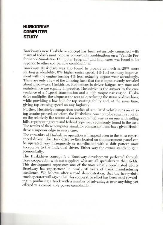
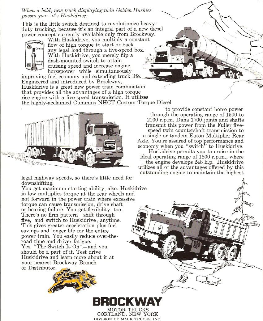
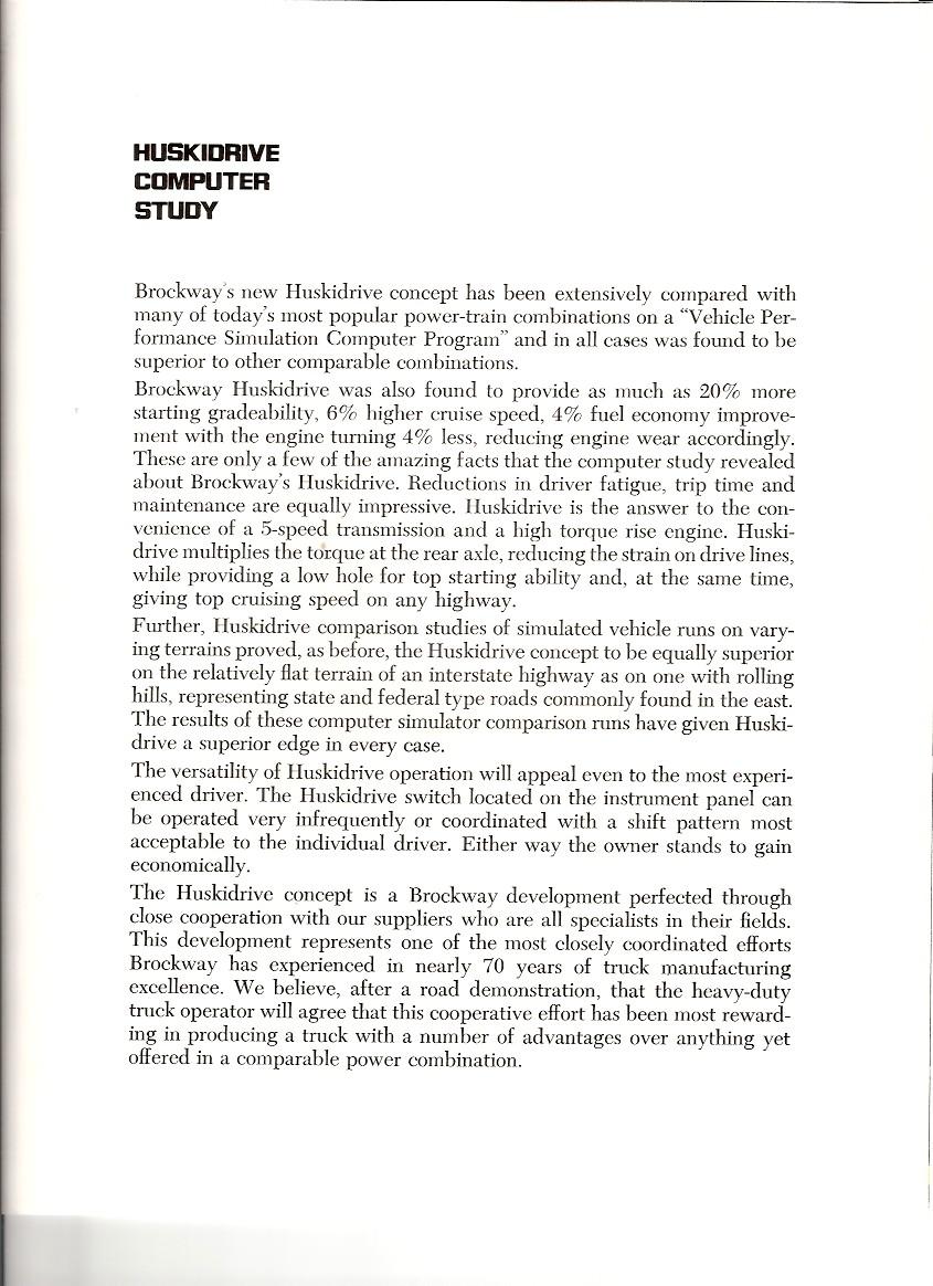
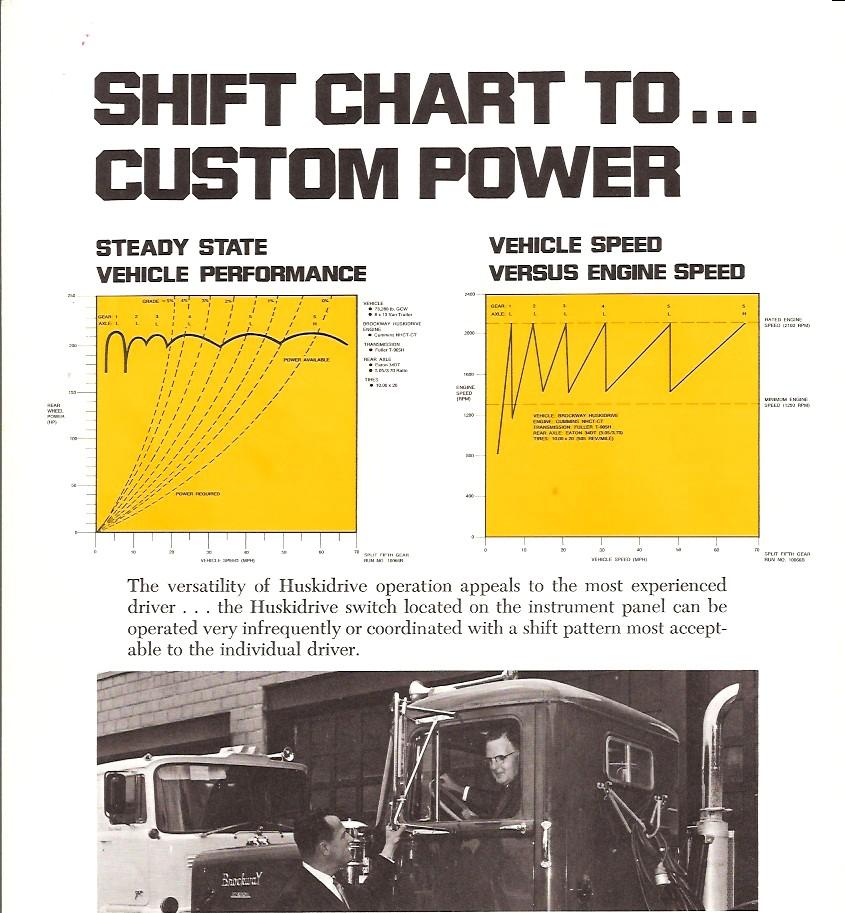
Here is a copy of the factory brochure on Huskidrive... The engine in my 68 360 Brockway came out of a 69 361 Huskidrive Brockway and it's an NHCT 270 (like mentioned above...)


-
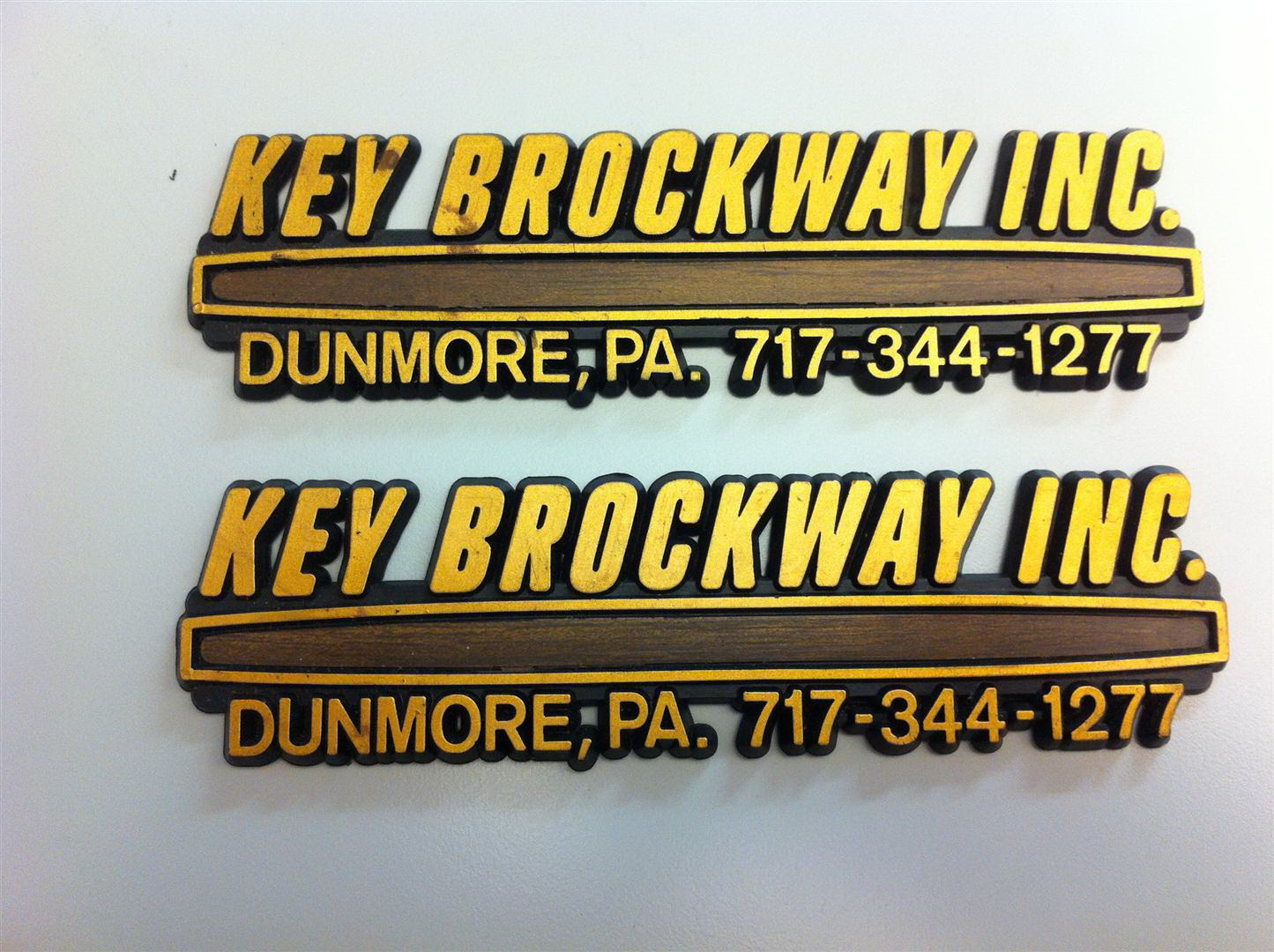
Thanks 57 bcr. The reference to the Bolus story in the Oct 76 issue was in the Sept 76 issue with this cover... The dealer was actually called "Key Brockway"
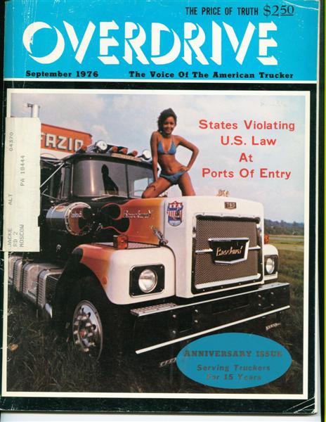


.jpg.bd5978834d747f642b94c2b918e31abf.jpg)
.jpg.8b14be40395d36fbf6b83dad08e79f26.jpg)


BMT Forum Logo
