


oldspwr
-
Posts
152 -
Joined
-
Last visited
-
Days Won
7
Content Type
Profiles
Forums
Gallery
Events
Blogs
BMT Wiki
Collections
Store
Everything posted by oldspwr
-
While I was working on the compression release I decided to replace something else. The fan support bracket that is mounted directly underneath the compression release bracket had (3) separate spaces under each bolt to compensate to the jake height. I decided to remove these spacers and make (2) new ones... This is what I started with... And these are what I made... And here they are installed... Well that’s it for now...
-
Someone has also welded an extension on the factory bracket the rod or cable would attach to, so I decided to cut that off since it wasn’t needed... I also decided to use a cable instead of the rod. I had a box full of older PTO cables and found one that was in tired shape. The first 4’ was in great shape but the last 3’ was wore through in a spot, etc. So I decided to use that cable. In order to use the cable, I turned a 5/16” bolt down in the lathe, drilled (2) holes in it, (1) for a cotter pin and (1) for the cable to pass through. And then I found (2) 5/16x18 nuts with washers attached to them... And this is what I wound up with... When I was done fabricating everything I gathered all the parts up and bead blasted them... At that time I also discovered that the original bracket was cracked and that was some of the reason for all of the play... I then assembled the new pieces using new 1/4" roll pins and painted everything... More to follow...
-
Thanks for everyone's comments, now its time for an update... In addition to the power steering there were a handful of other items that I wanted to take care of. The was a long 1/4" rod that was used for the compression release. This rod now hit the bracket I made for the power steering reservoir. I had posted a question earlier about play in the linkage so I felt it would be a good time to correct everything. This is what I started with... After disassembling everything, this is what I wound up with... In the upper left hand corner of the pic you can see an NOS compression release bracket that Stan helped me out with (Thanks Stan!!!) You can also see a piece of 1 1/2” round stock. I decided to use this piece of round stock to replace the pieces that were originally installed when the jake was installed. I wound up turning this piece in the lathe to make my own extension... When I was done turning it in the lathe I drilled a hole in the middle to fit over the original piece and then drilled (2) 1/4" holes to accept roll pins (in lieu of bolts...) For comparison, this is what the factory install looked like... And here is what my extension looks like for the added height of the jake... More to follow...
-
Hi Brocky... The fire house is coming along real nice. Unfortunately I didn't get a great pic of it but I'm sure someone did. This is all I have... The field was open because they needed a staging area for the fire works. Tom
.thumb.JPG.ad9c574f56d5050b9fdc8974615d338f.JPG)
-
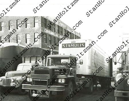
And this one is from Stan Holtzman's collection. I hope it's ok to share it if I credit the pic to him.
-
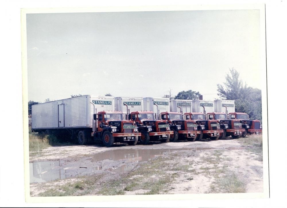
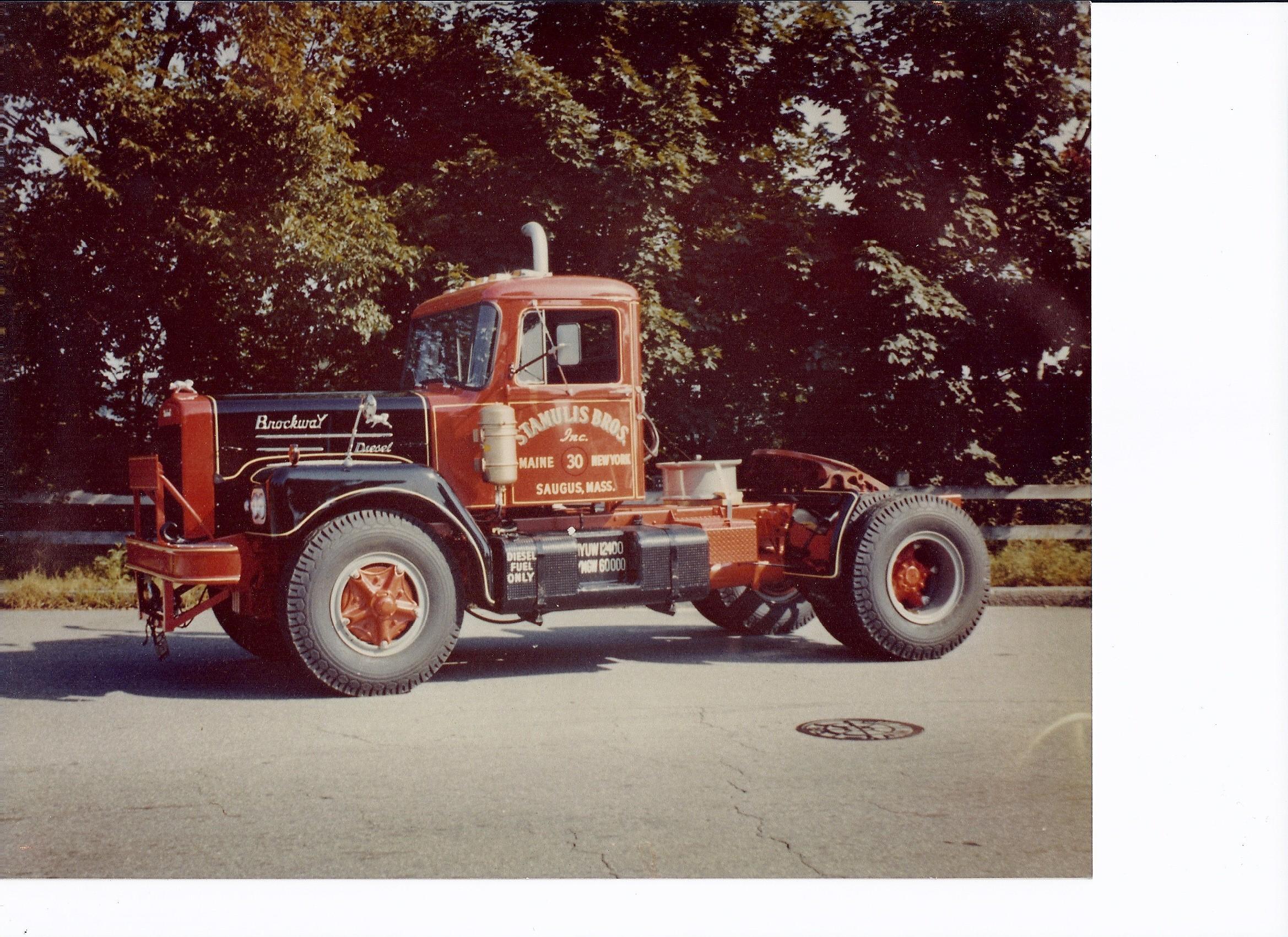
mowerman... you shared a pic of your Uncles trucks. Here are some pics I have collected over the years...
-
I understand the total count was 118. I believe the record was around 149? but with everything going on and border being closed, it was still a great turnout.
-
Thanks for sharing Eric, great videos!!!
-
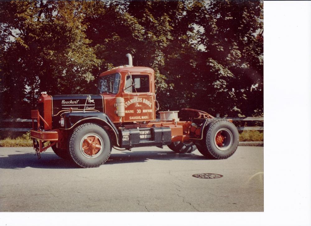
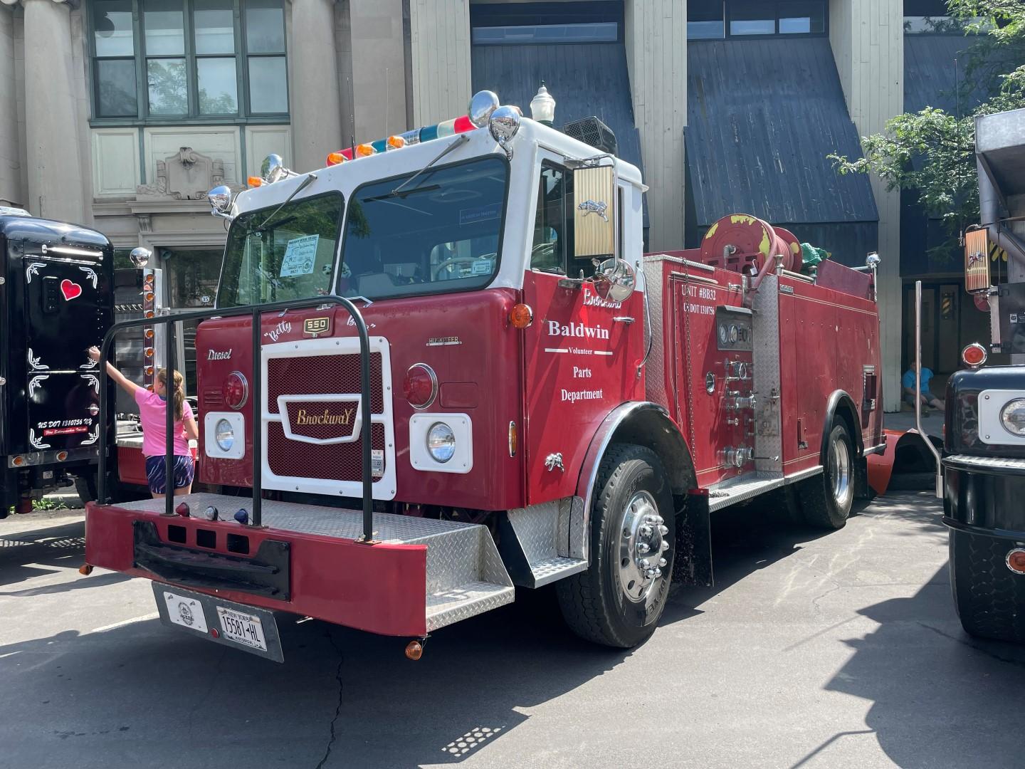
Hayseed... Ironically that's my truck! Its a 1970 E361T Brockway that my Dad and I restored a few years back. It was originally bought by Sears Oil in Rome NY and was S21. It has a 671 Detroit with a 10 speed RR. It originally had a 671N but now has a 671TAB. We also added factory power steering and replaced the rear springs with a Neway air ride. When I replace the 671N, I also replace the 4.10's with 3.70's. Tom
-
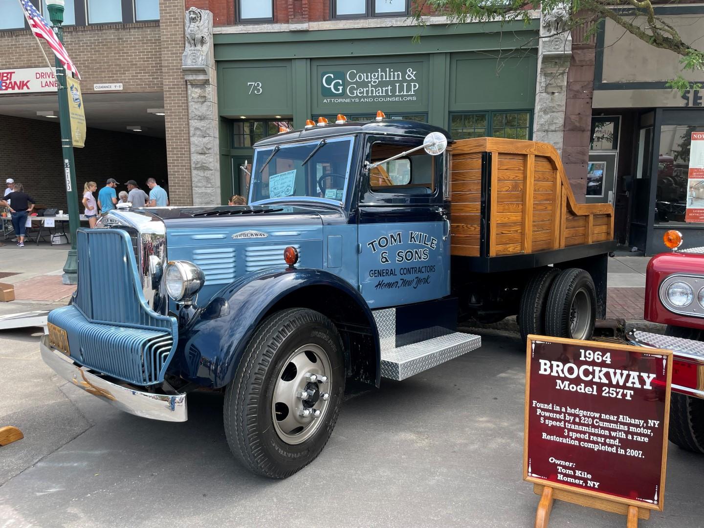
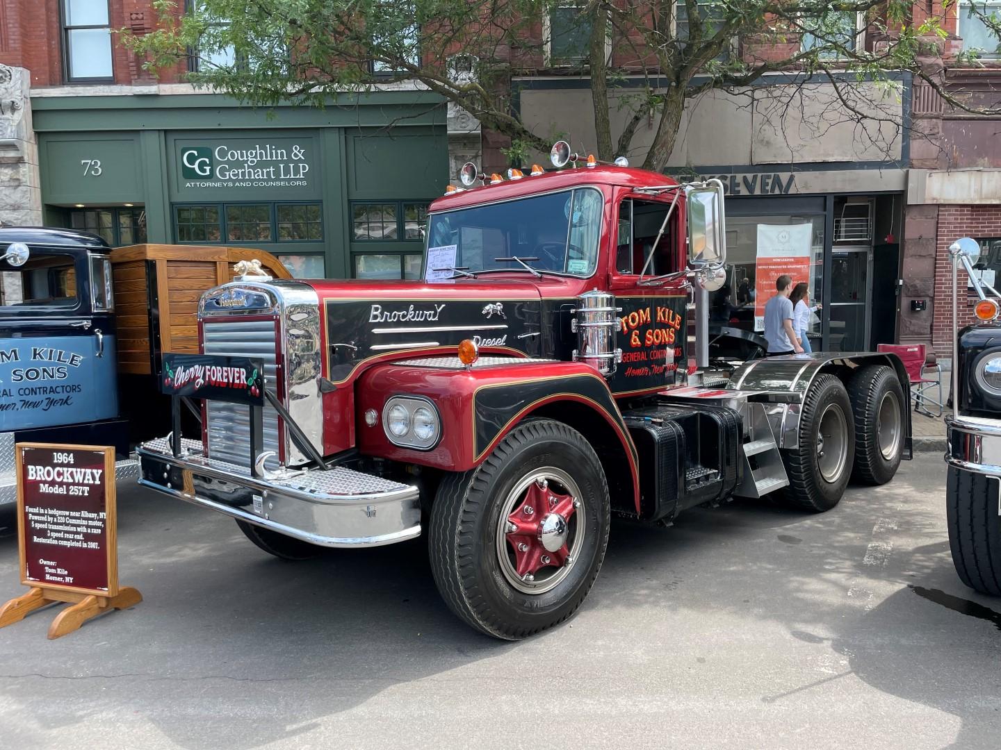
Paul is right, the 3 speed is for the 257 to the left of the truck in the picture. They are both Tom Kile's pics... Brockway's were very popular on the east coast but they did have dealers all across the country. So it's not uncommon to see them pop up in other areas of the country.
-
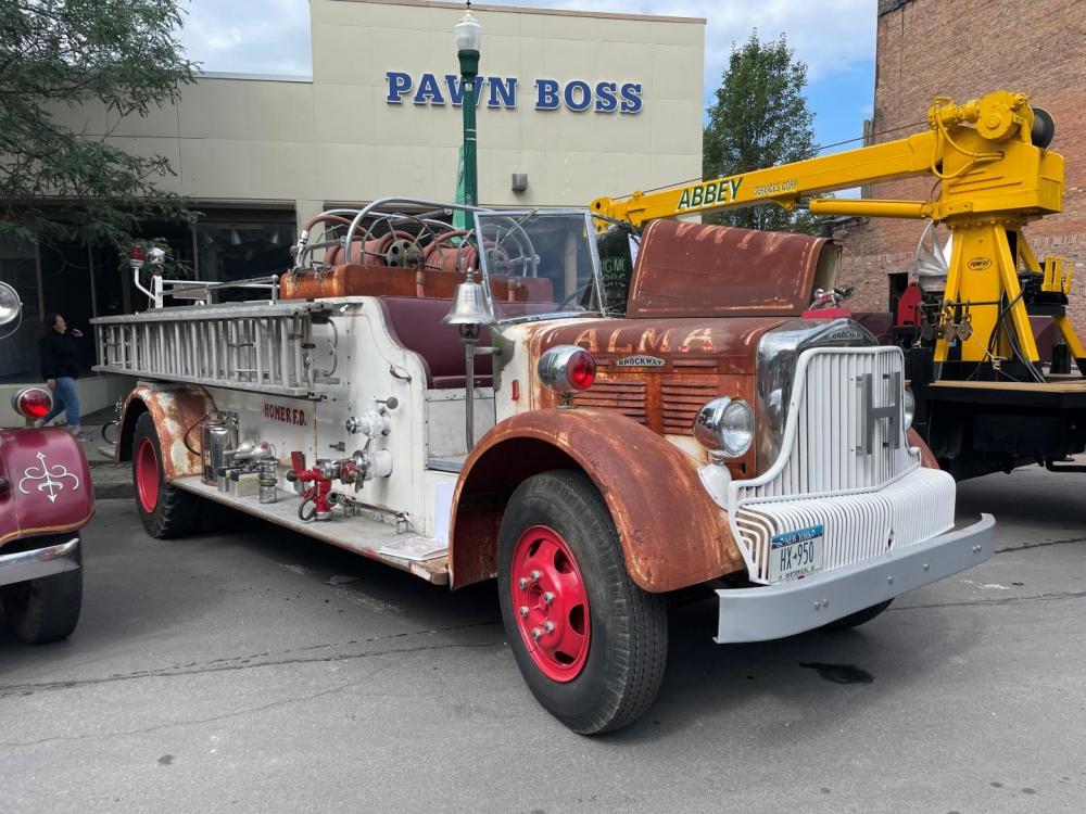
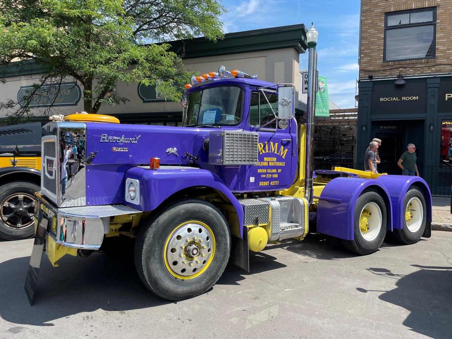
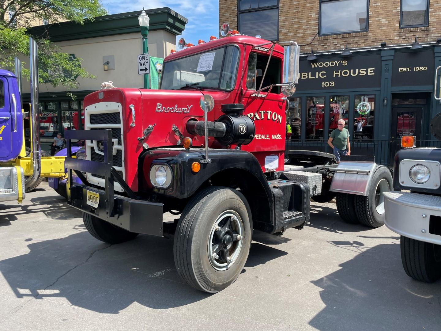
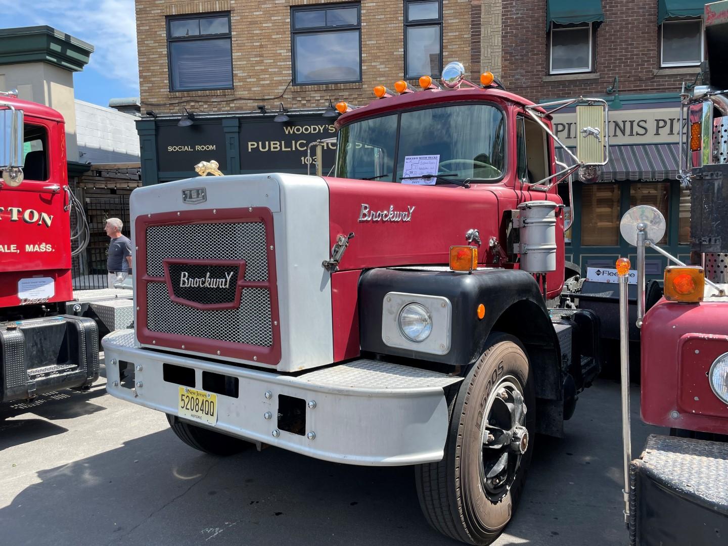
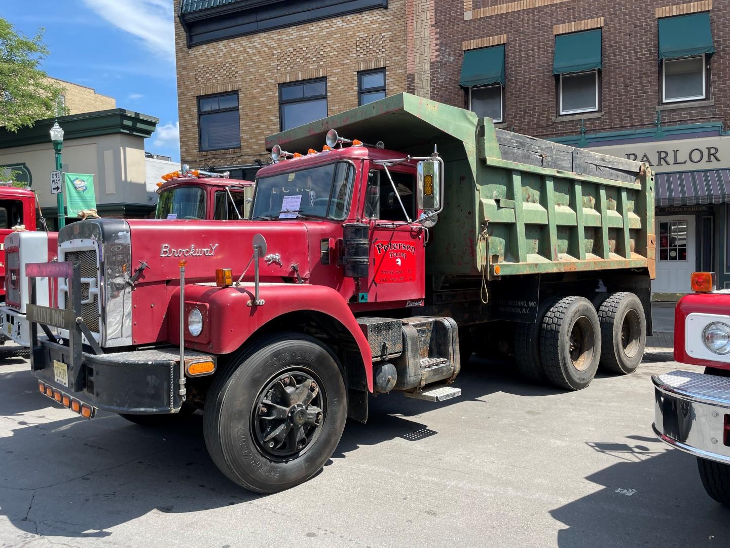
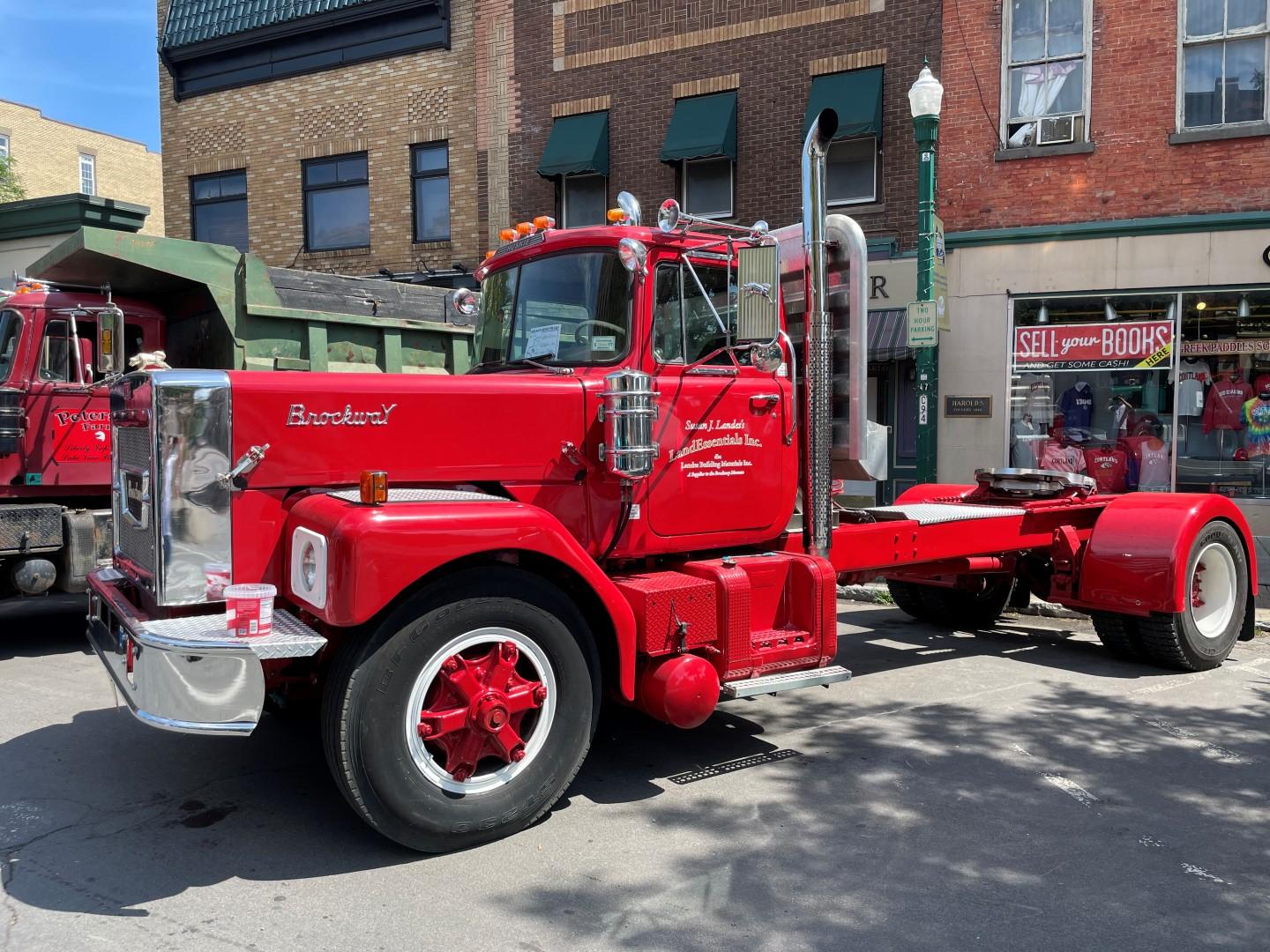
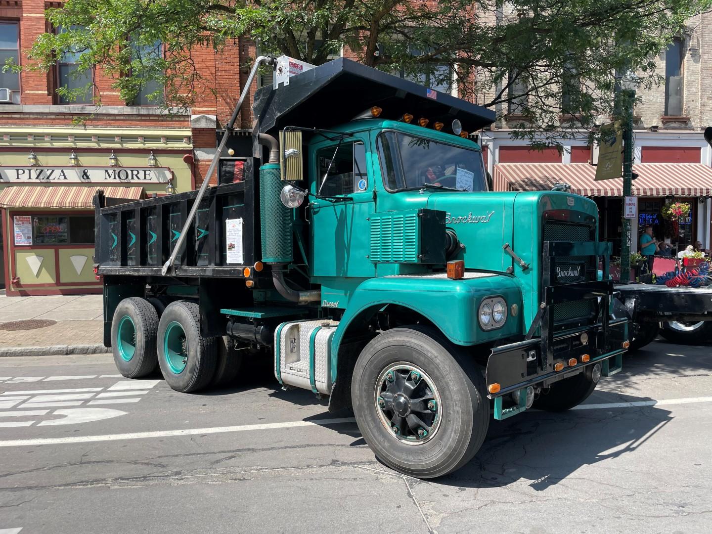
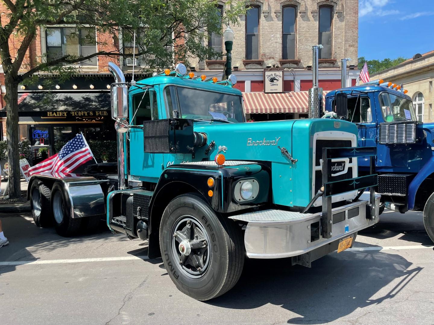
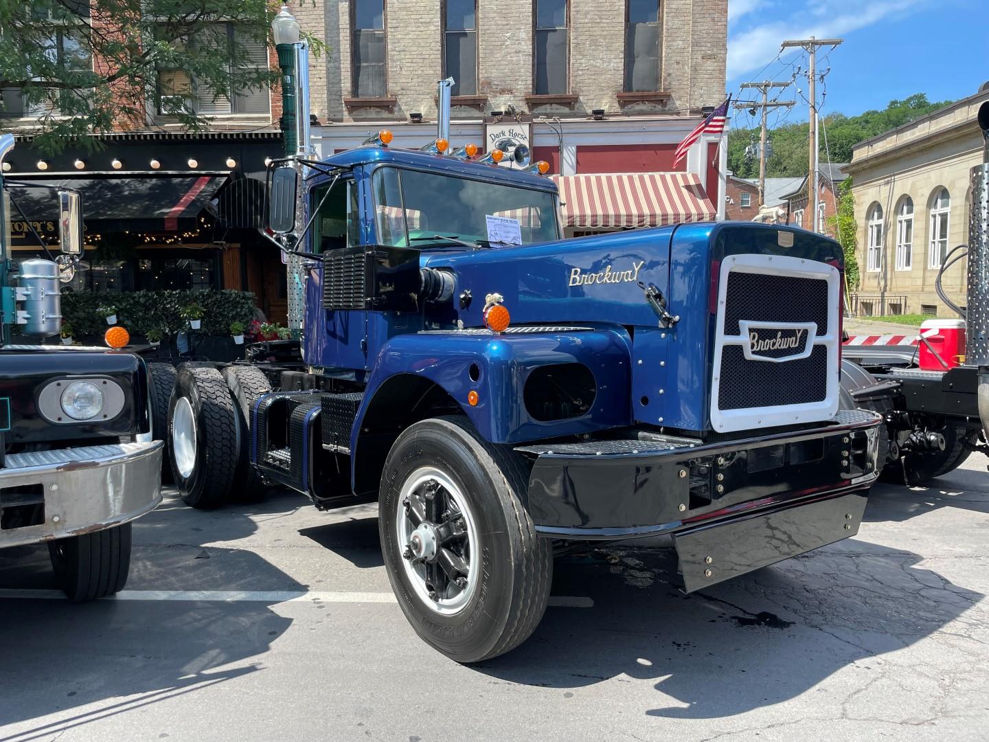
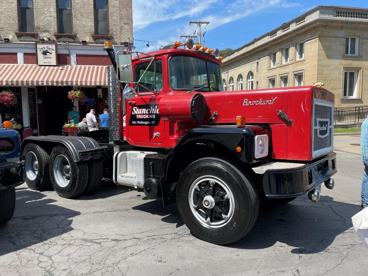
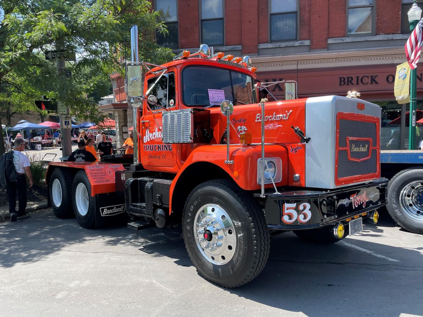
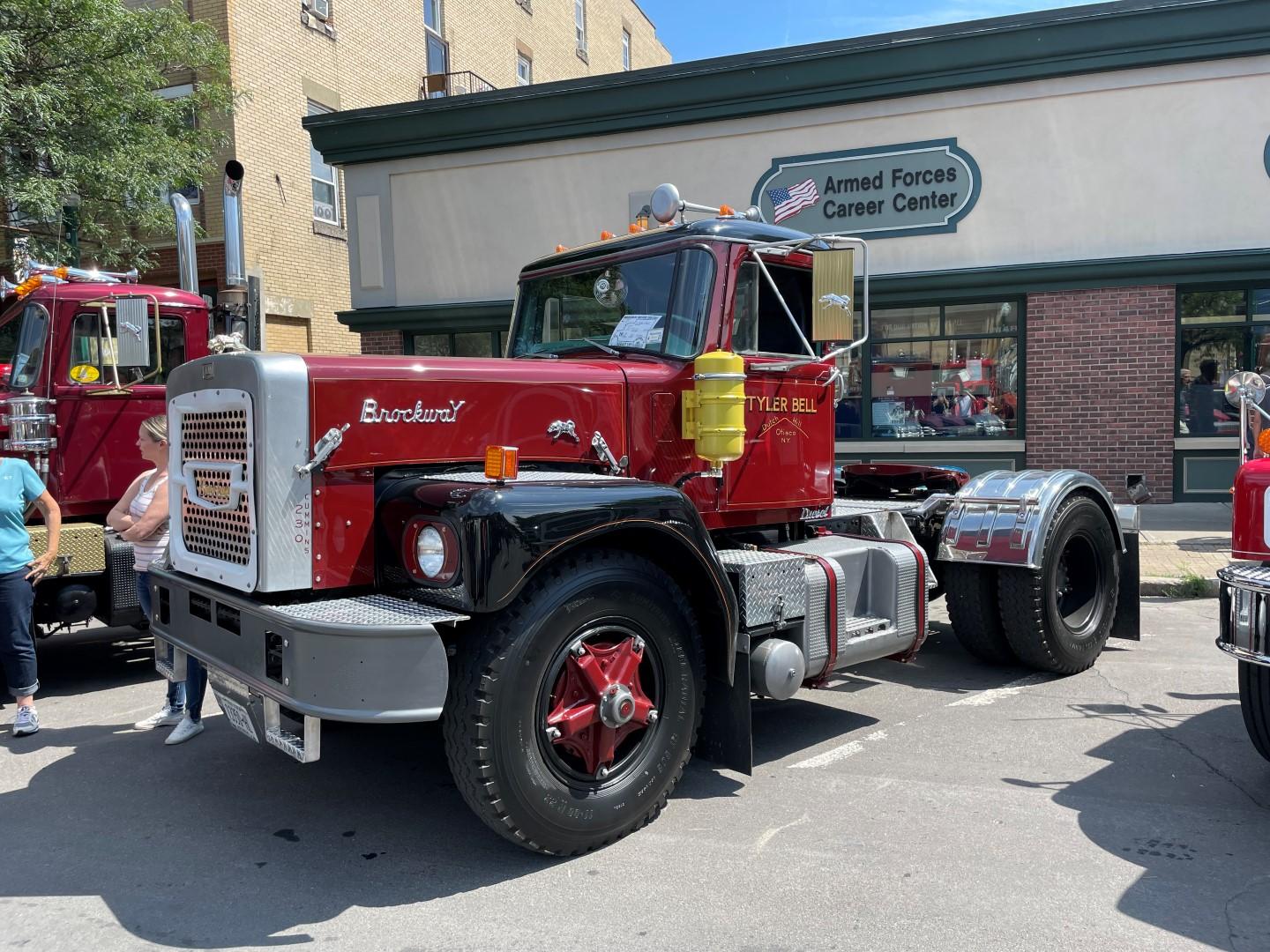
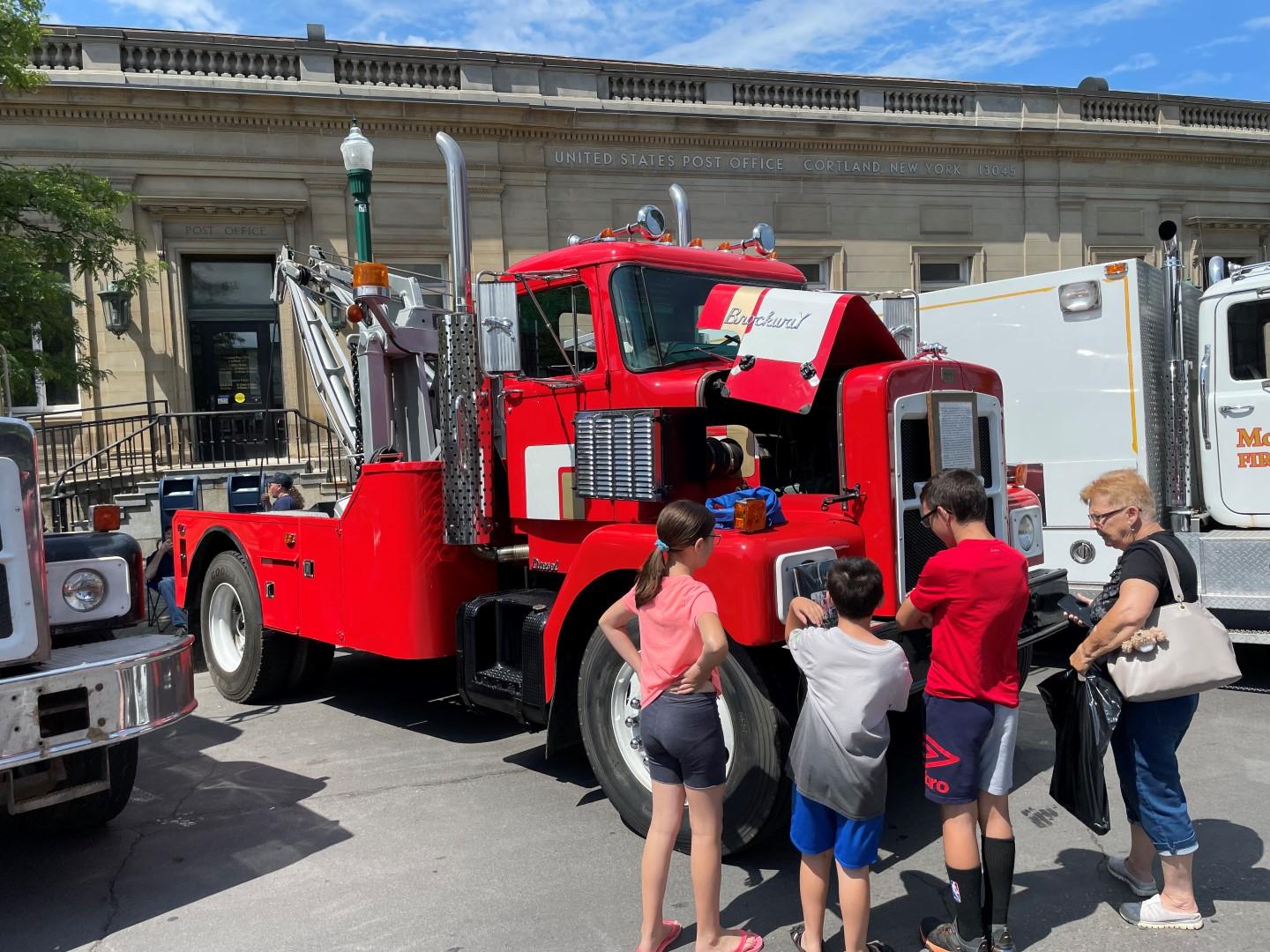
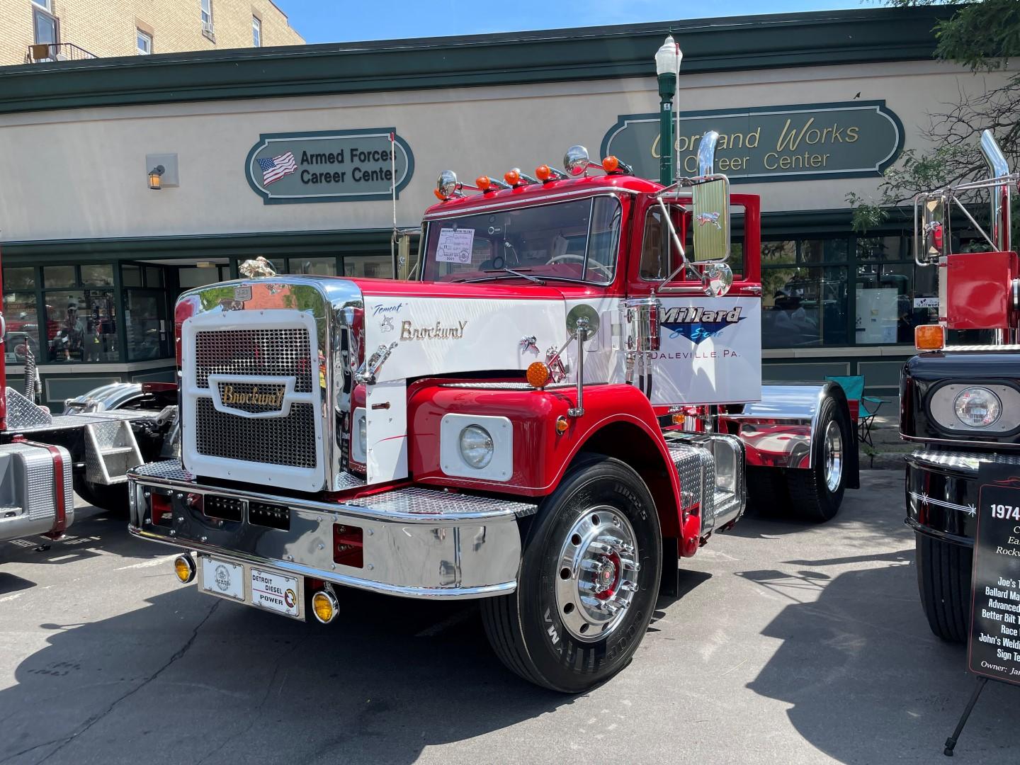
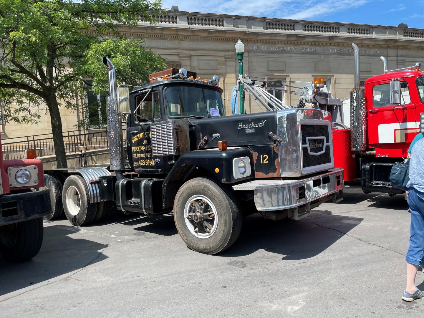
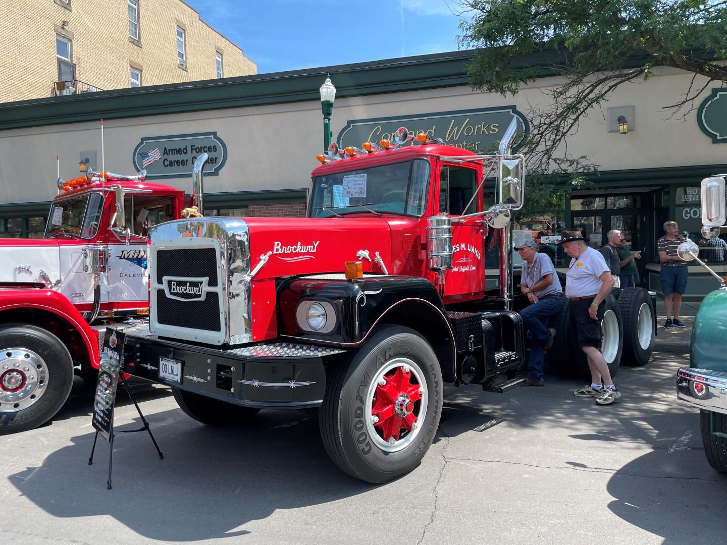
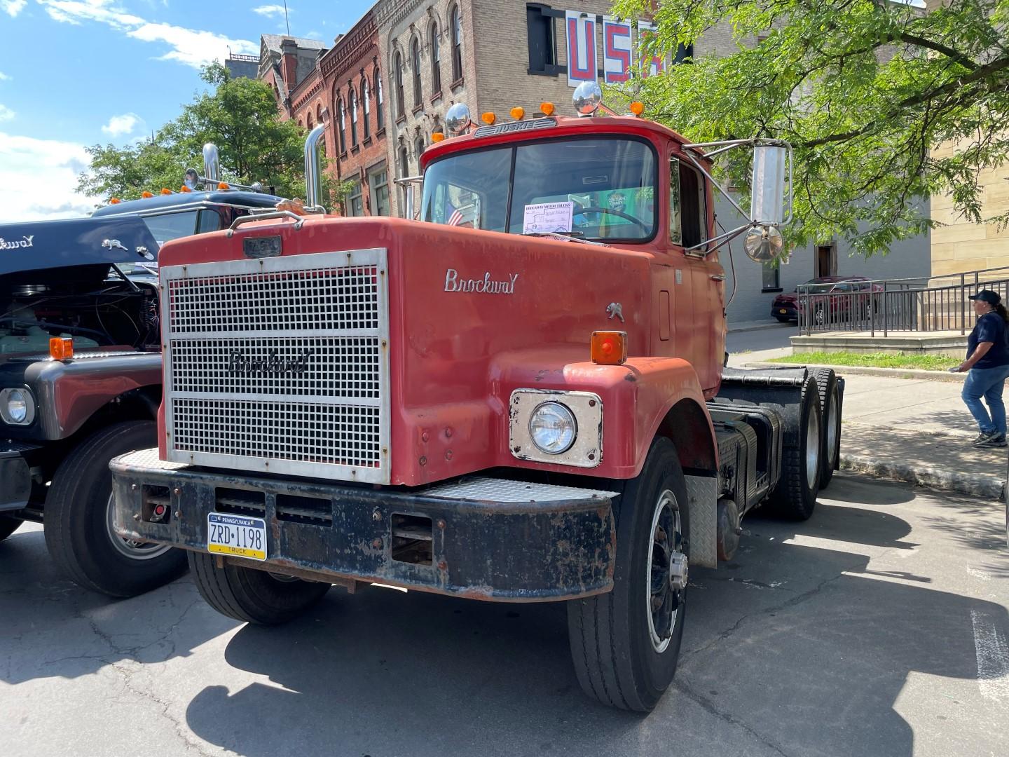
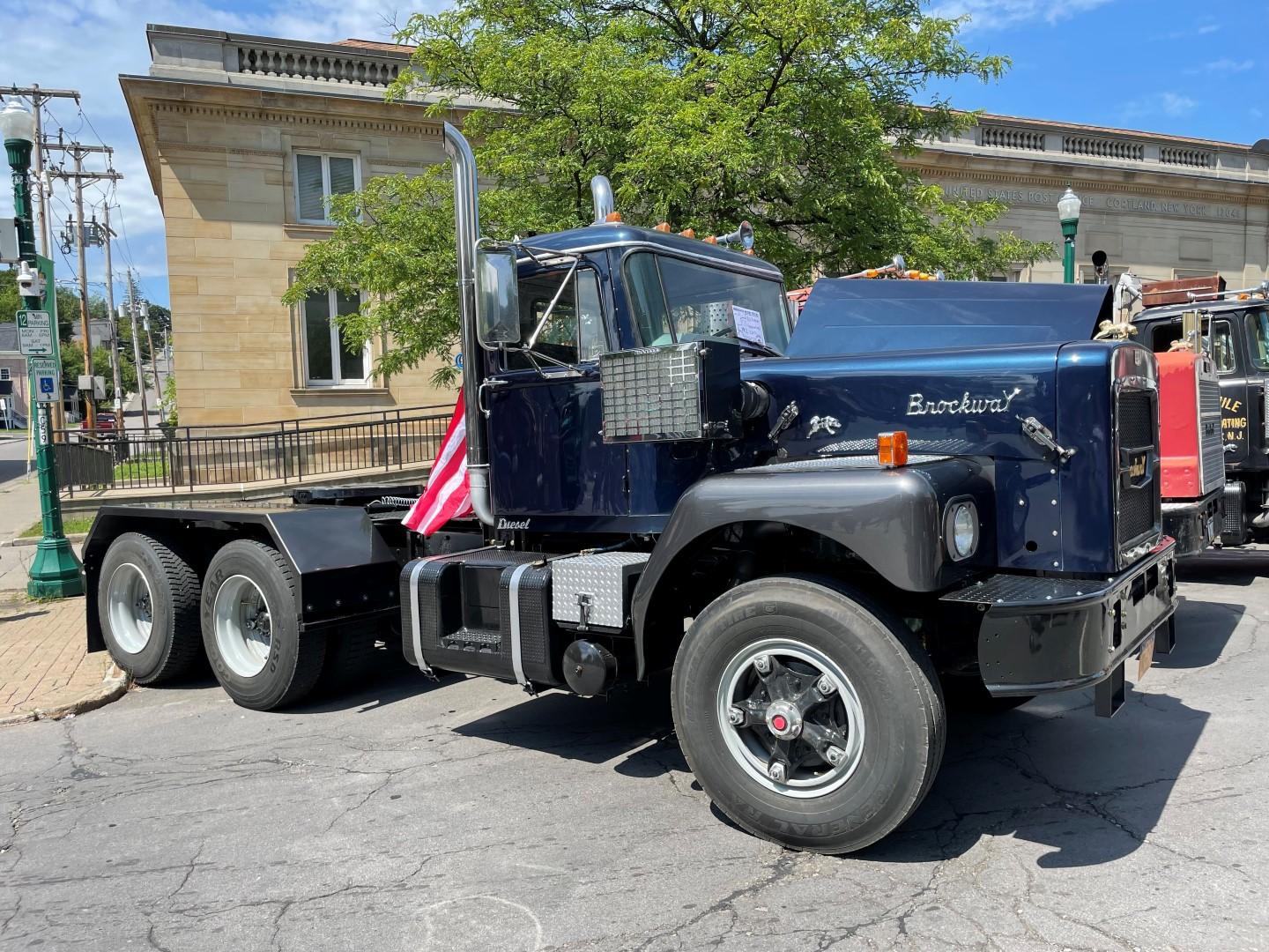
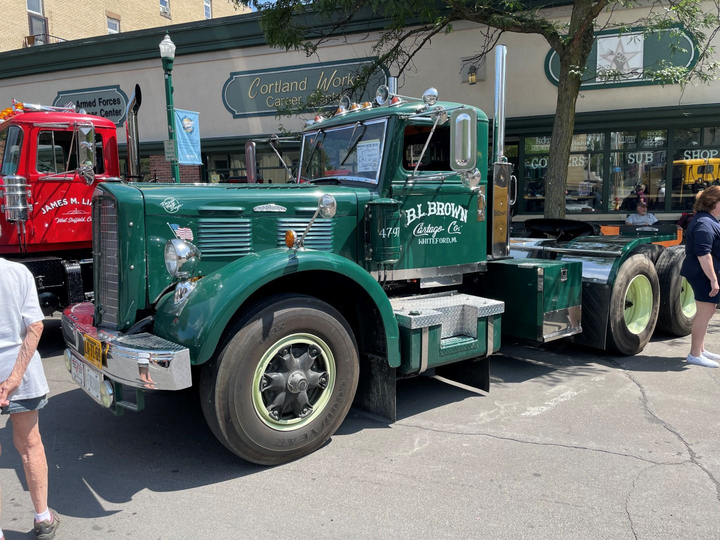
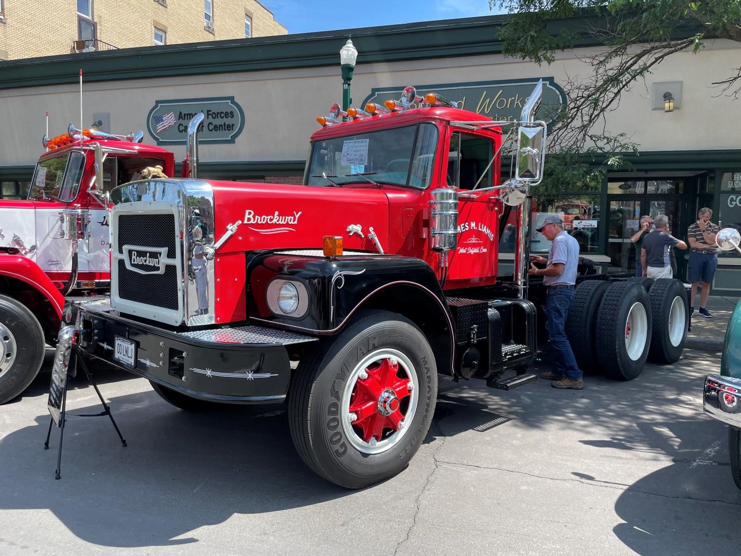
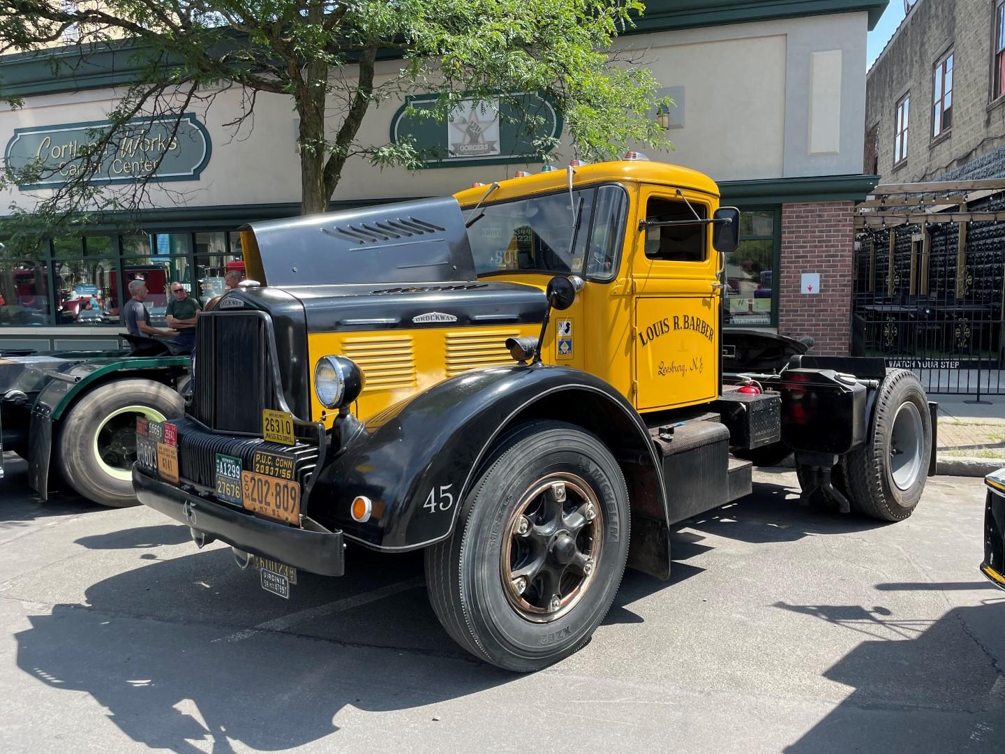
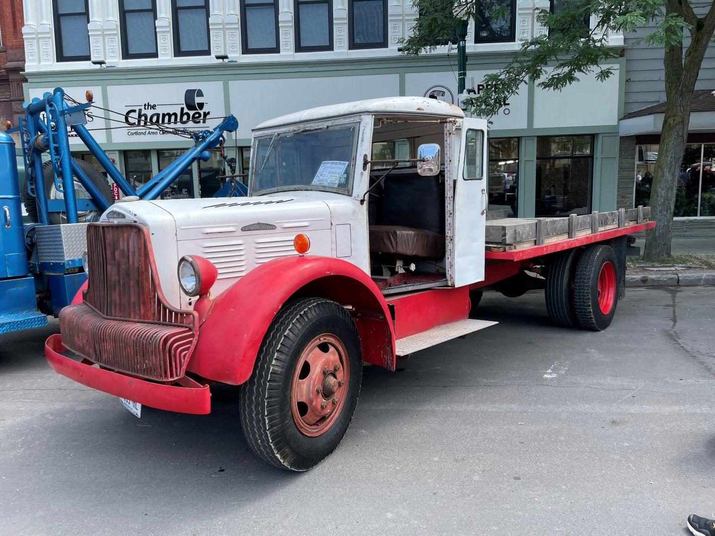
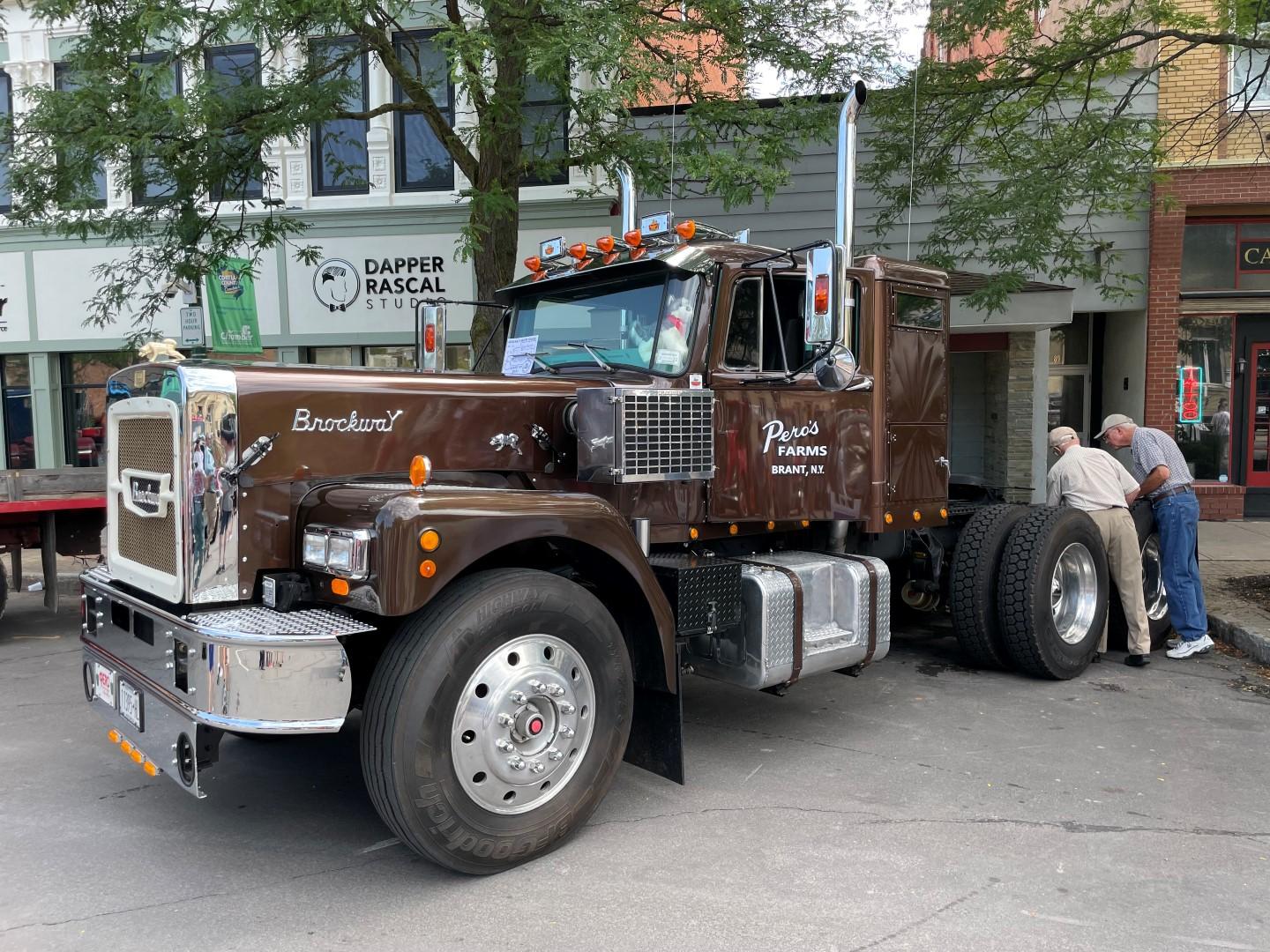
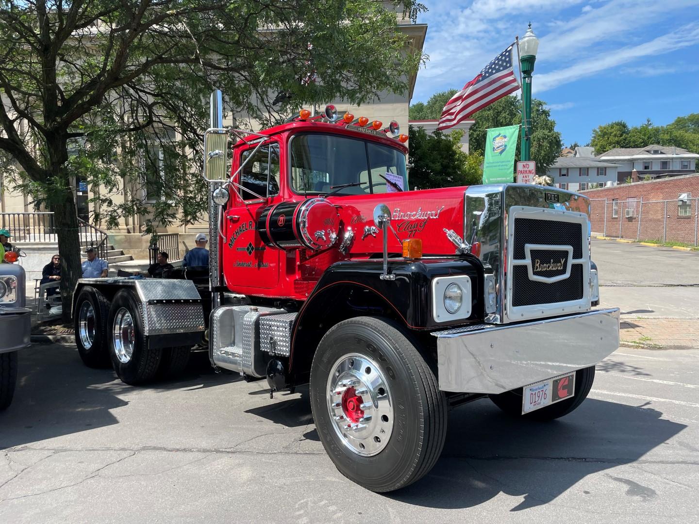
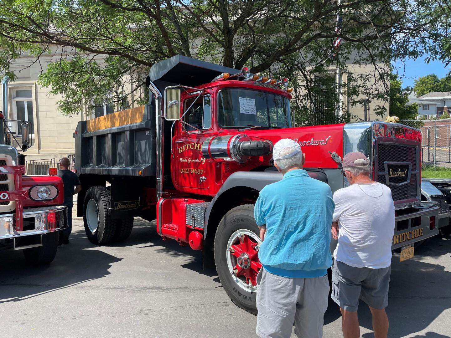
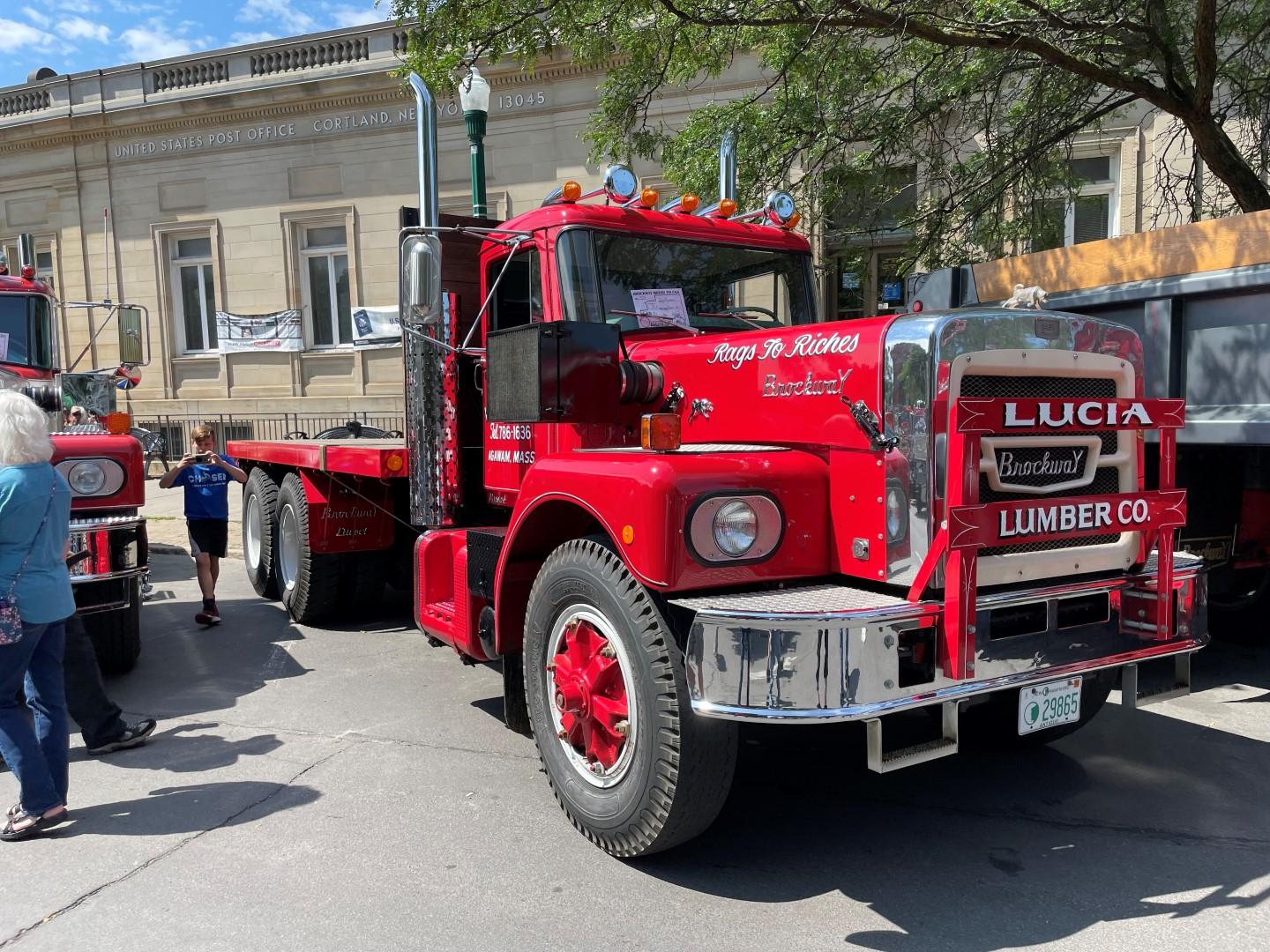
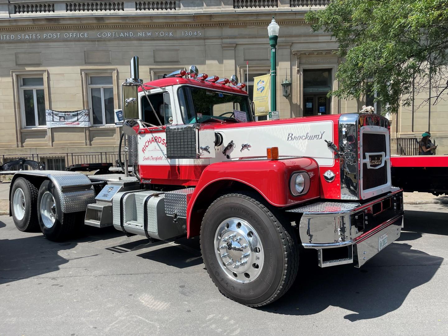
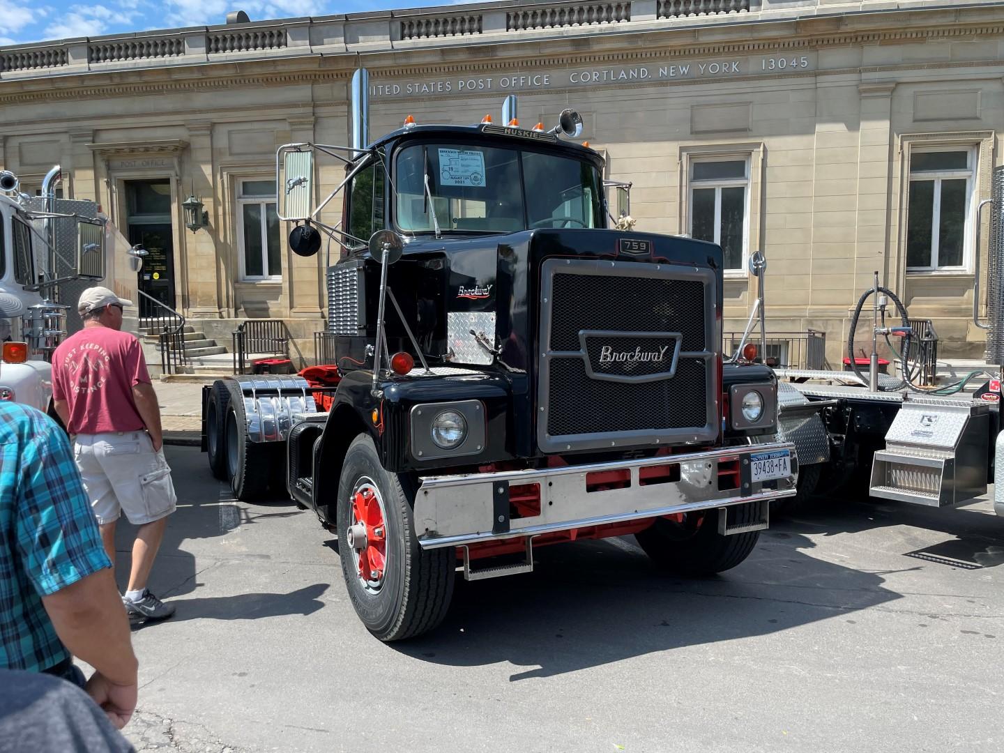
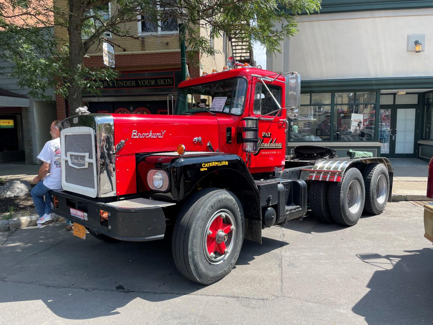
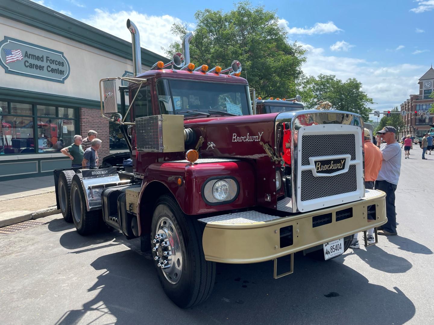
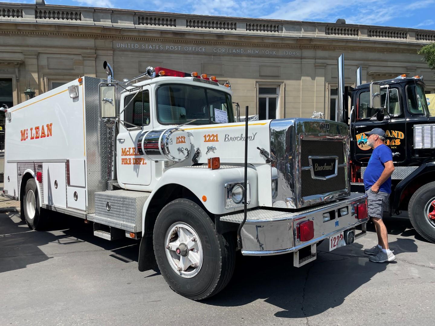
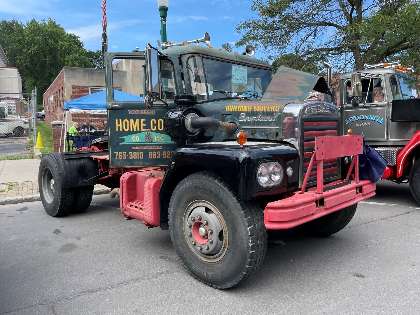
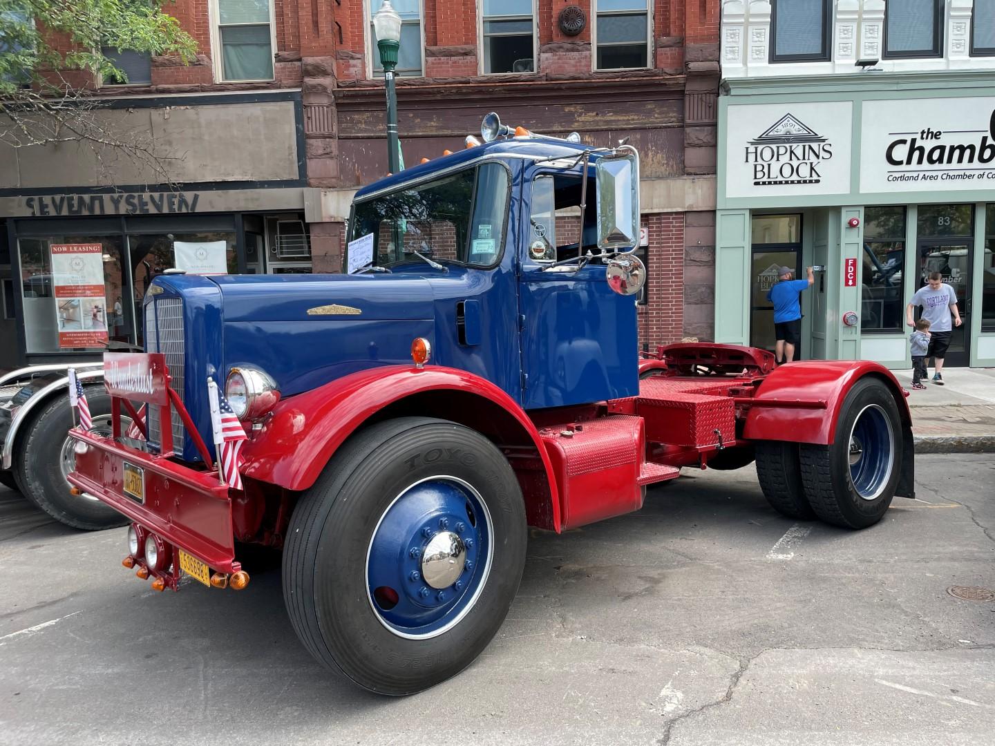
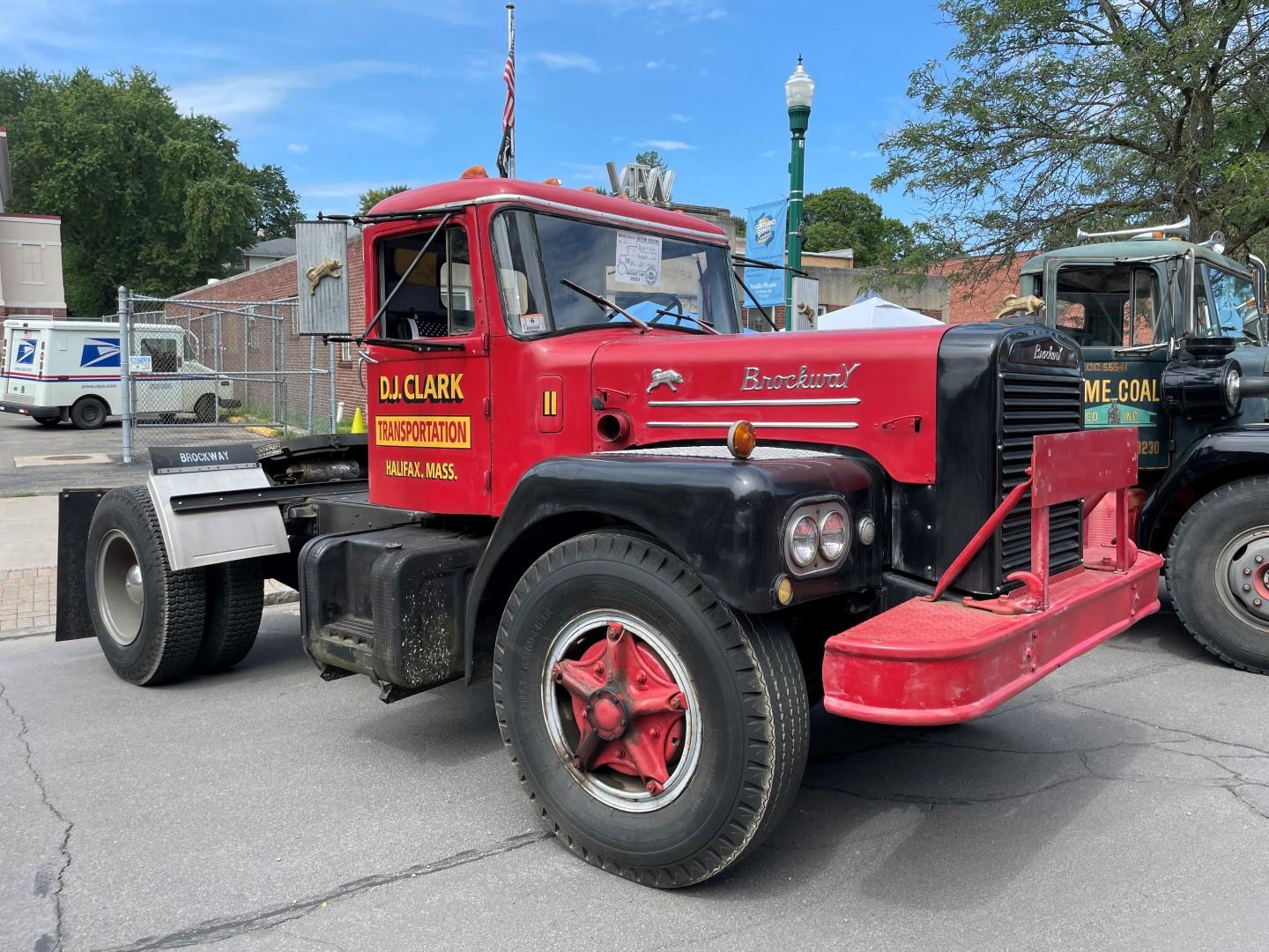
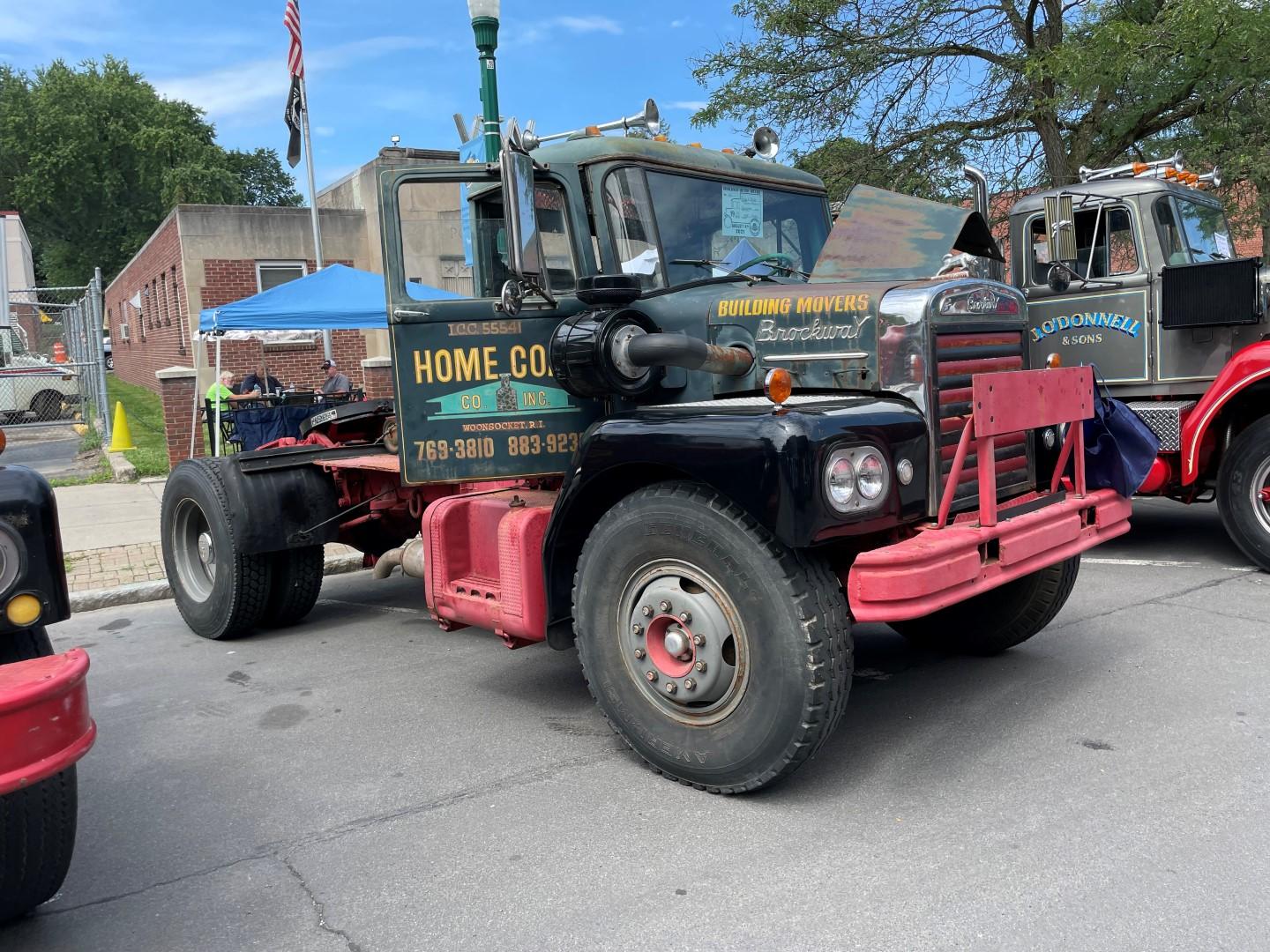
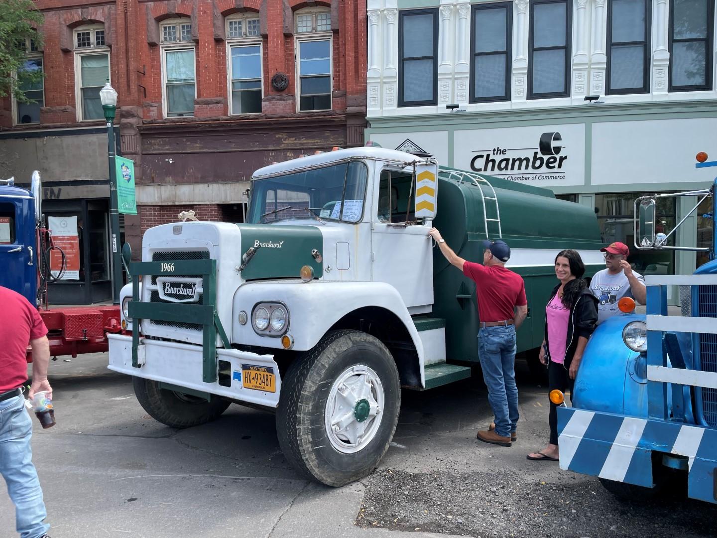
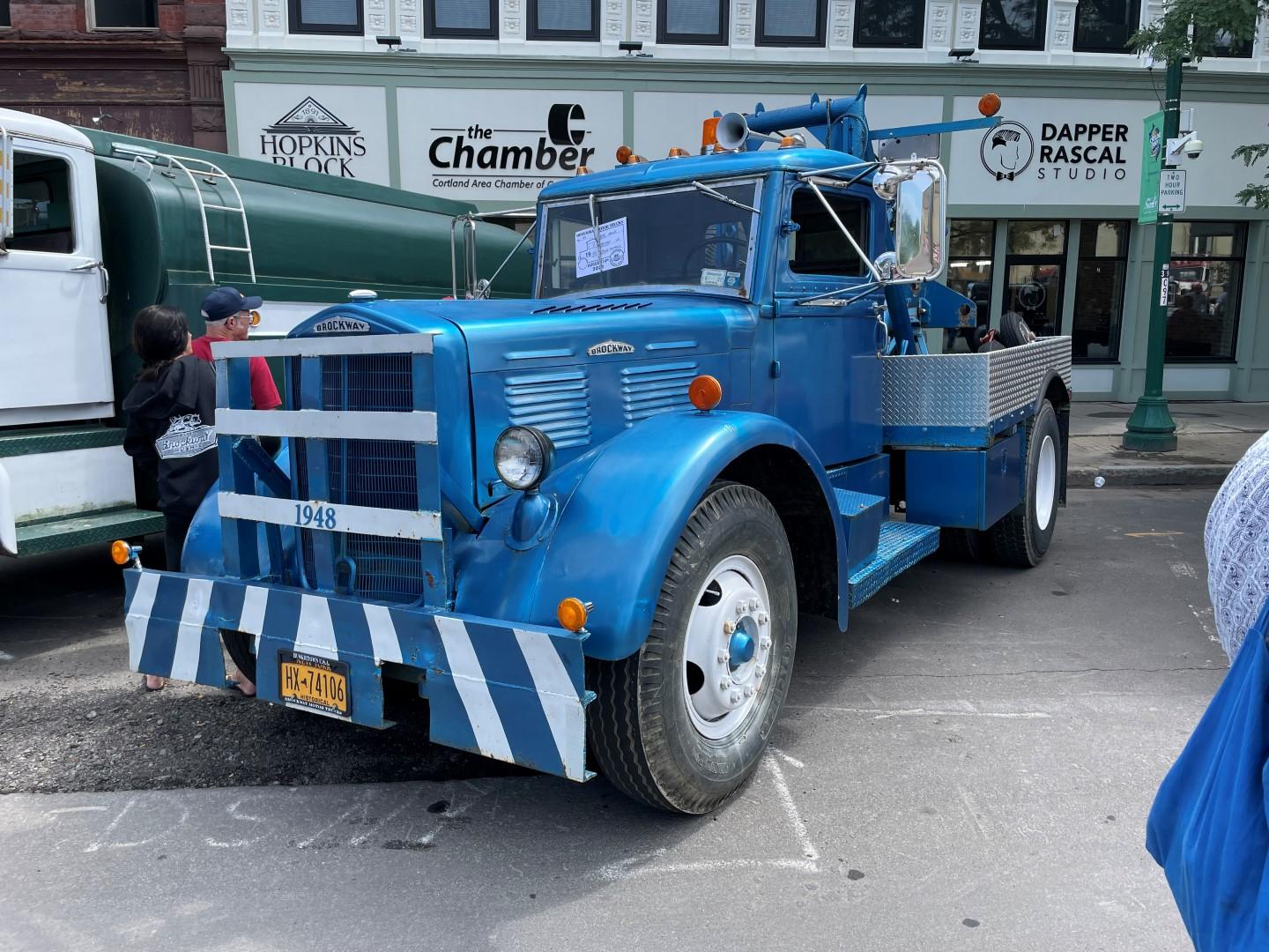
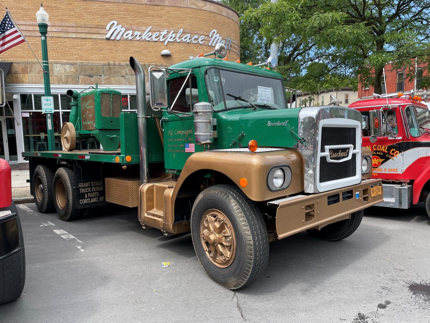
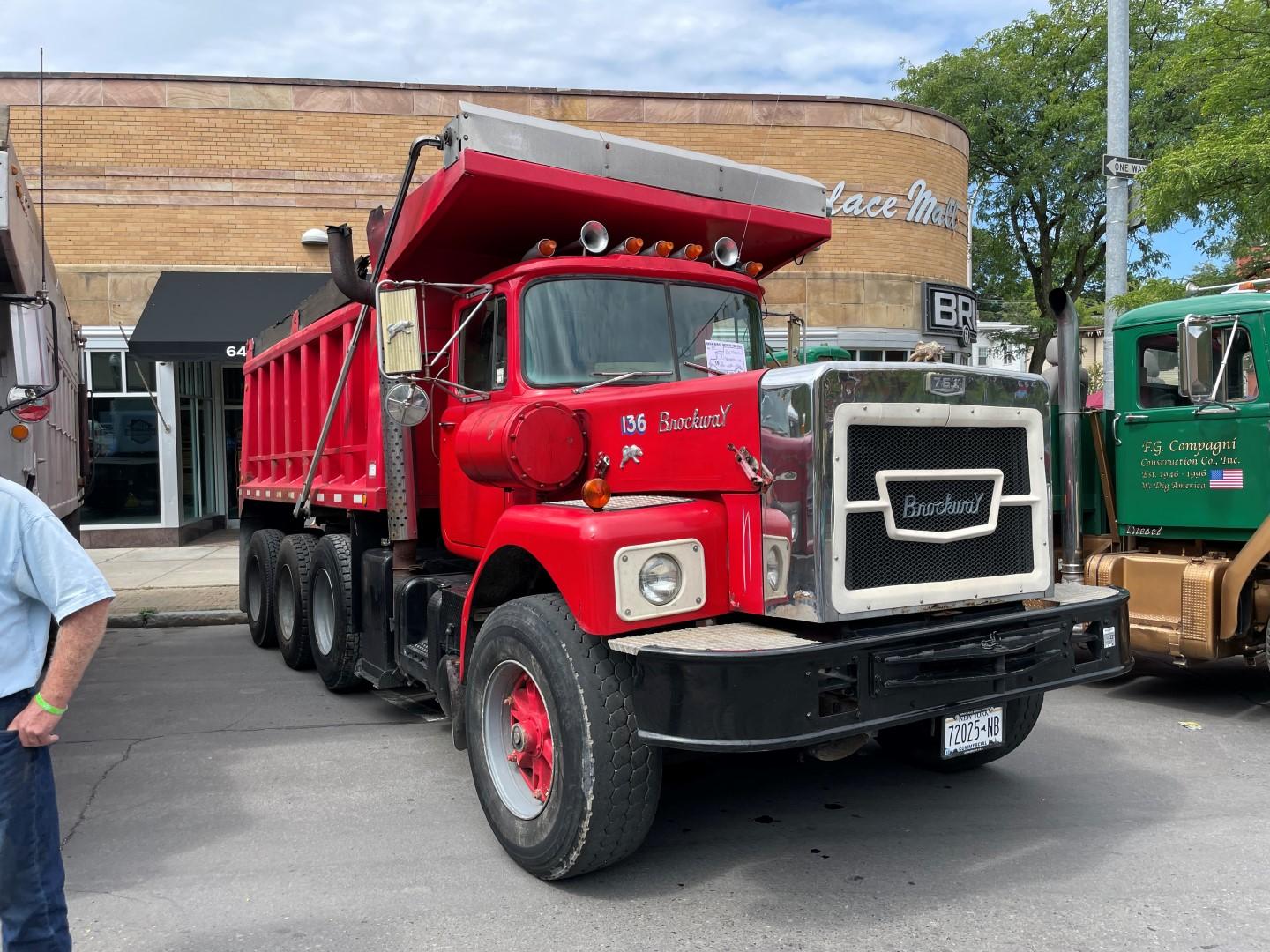
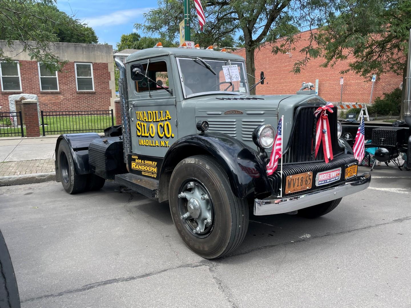
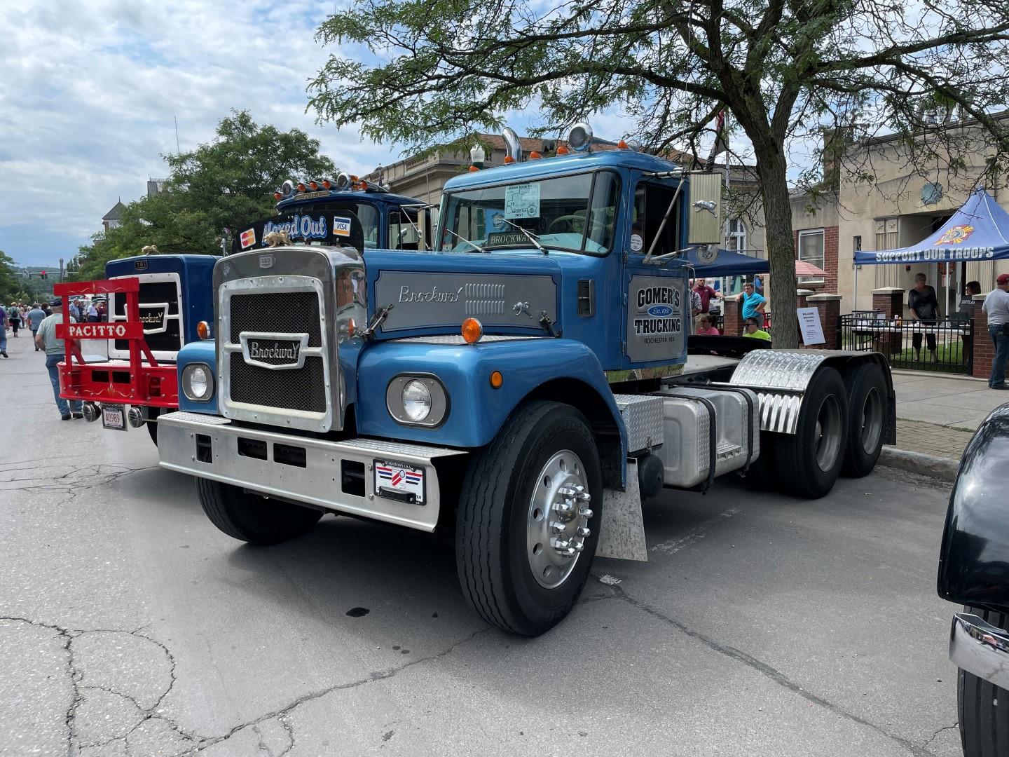
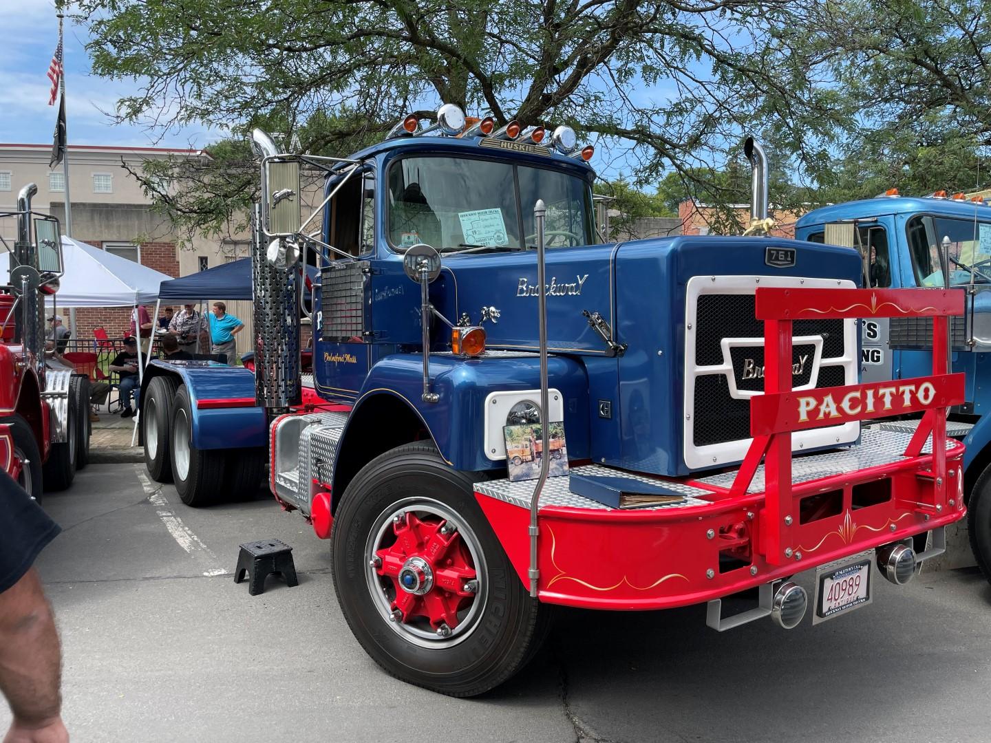
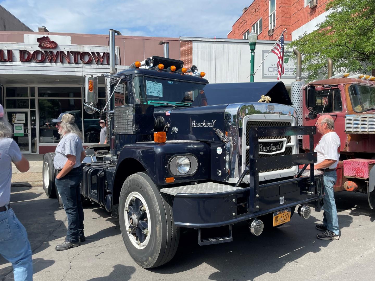
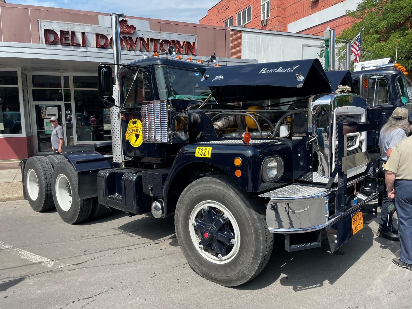
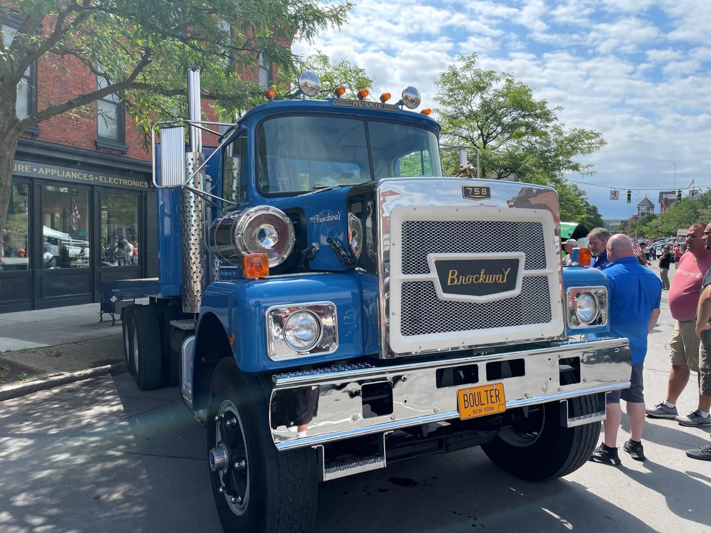
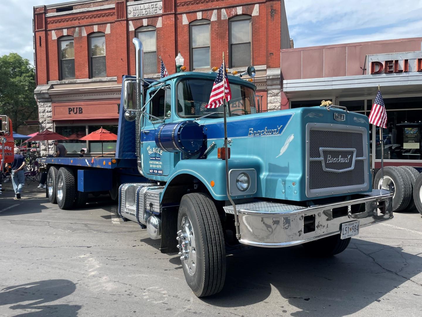
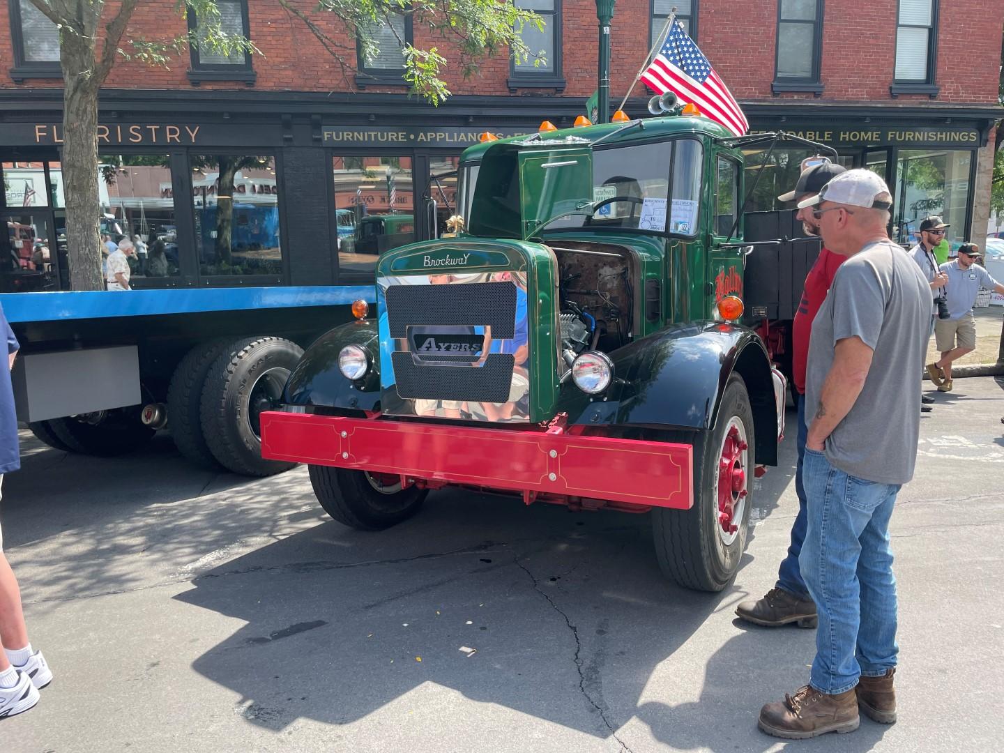
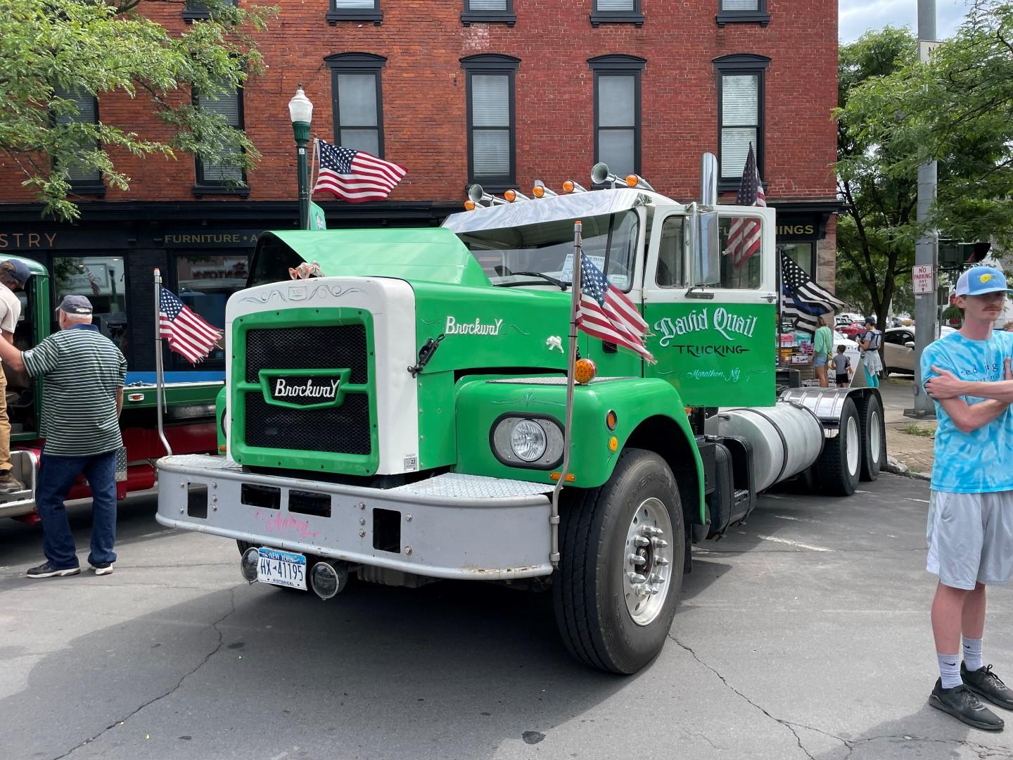
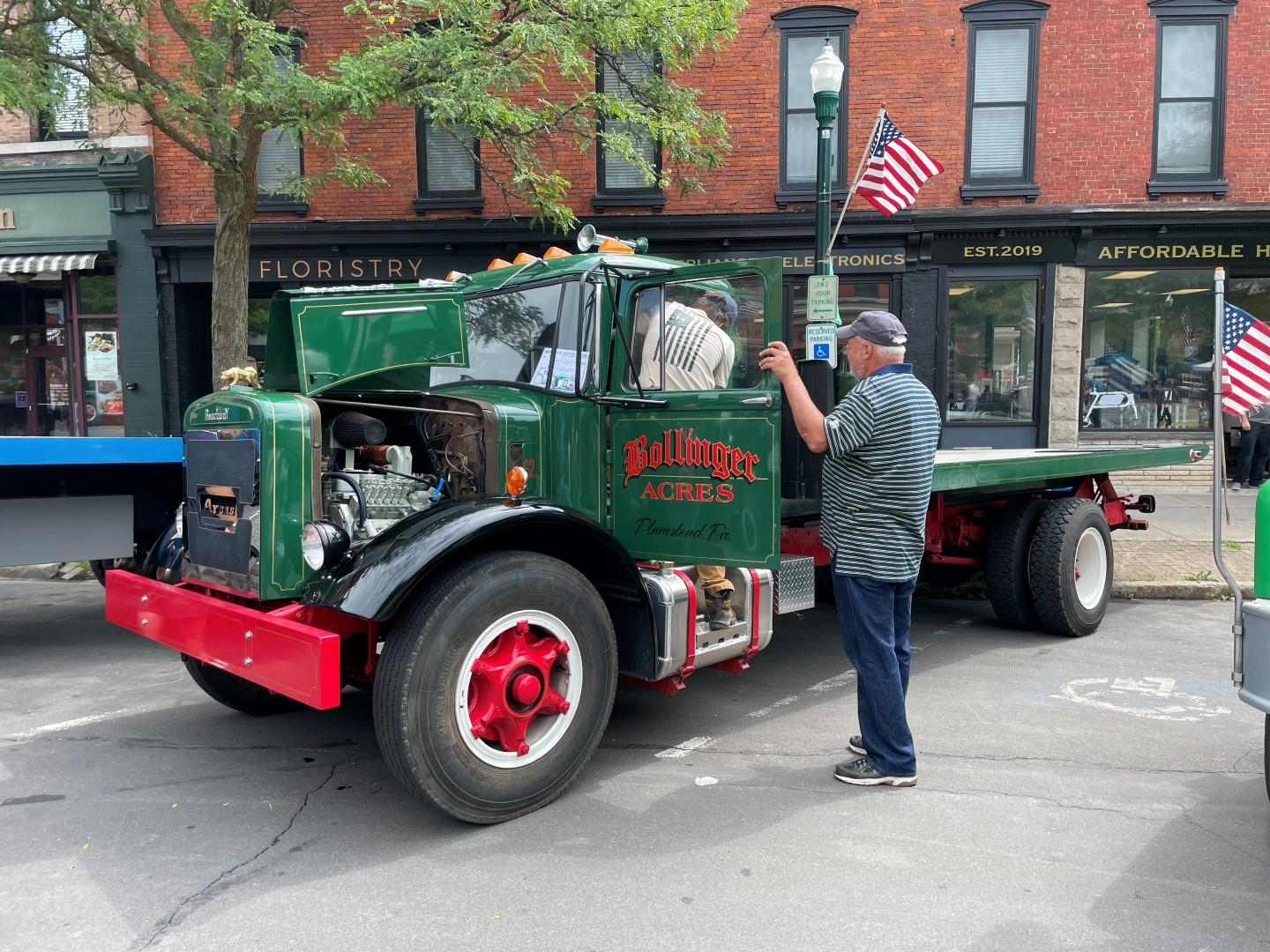
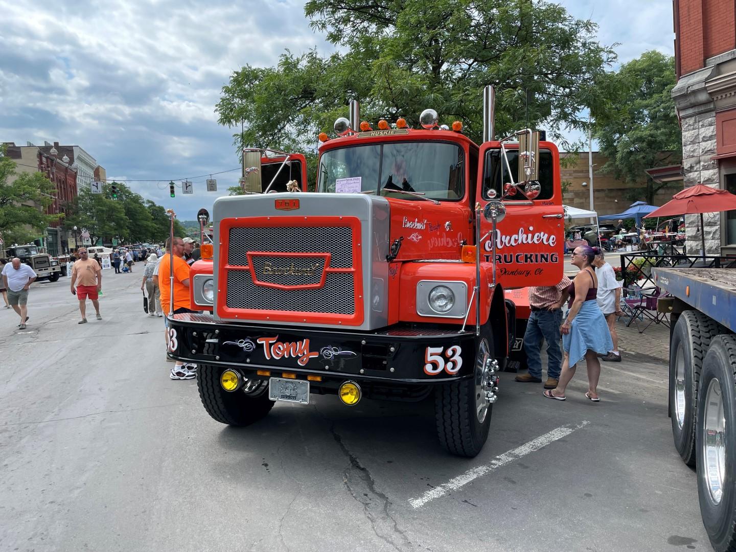
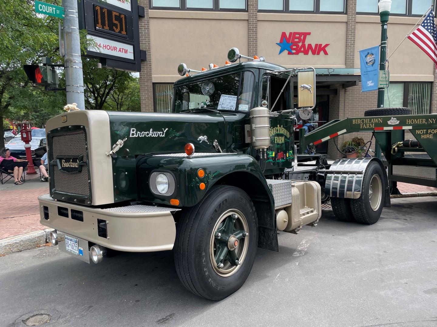
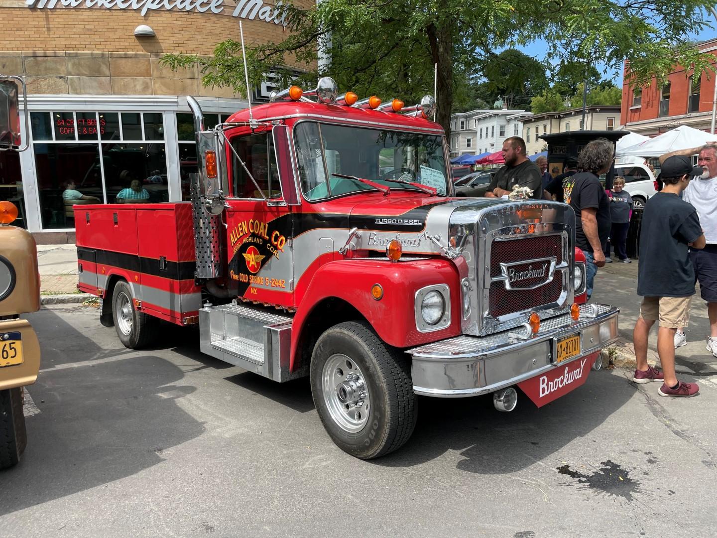
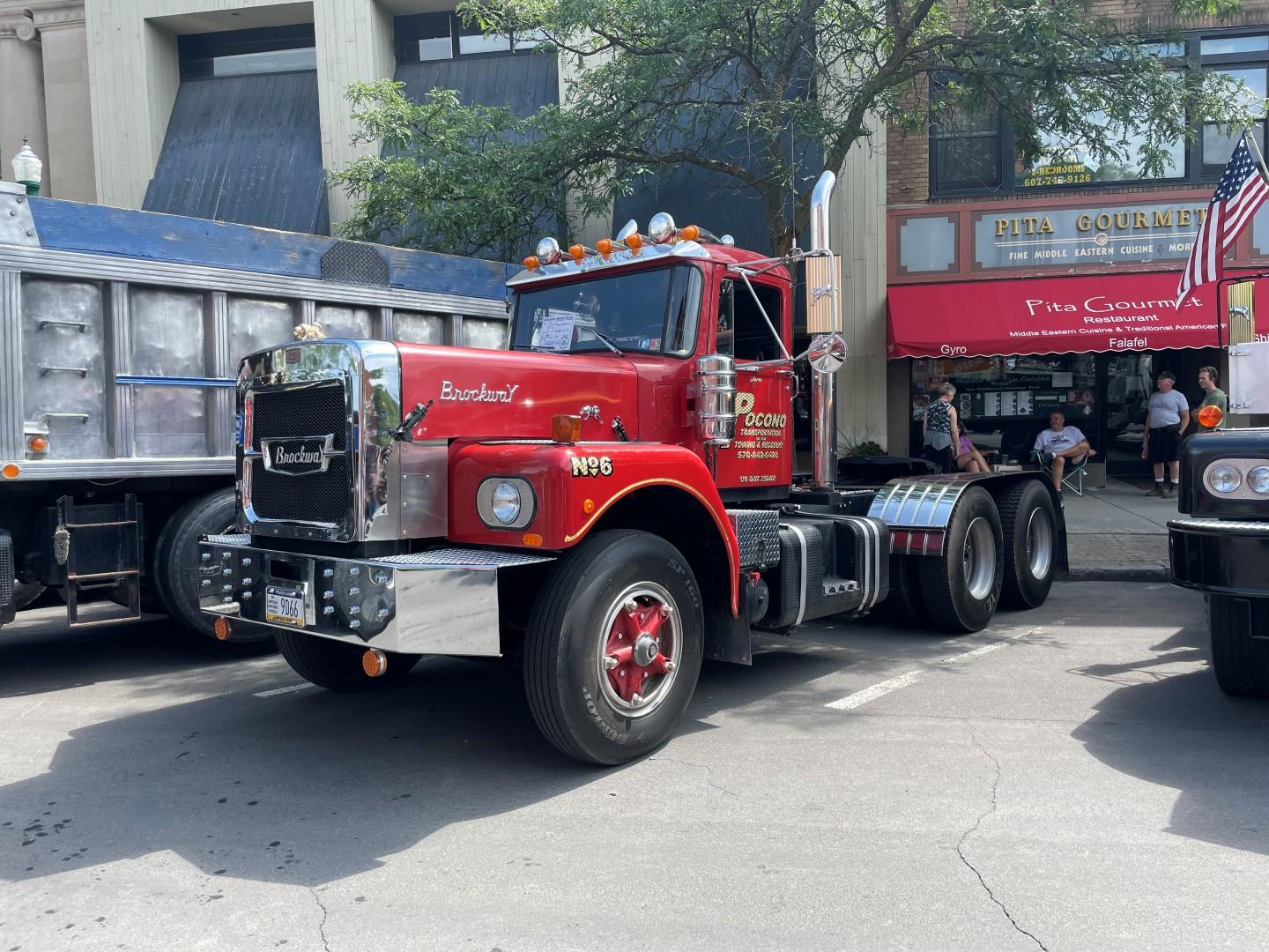
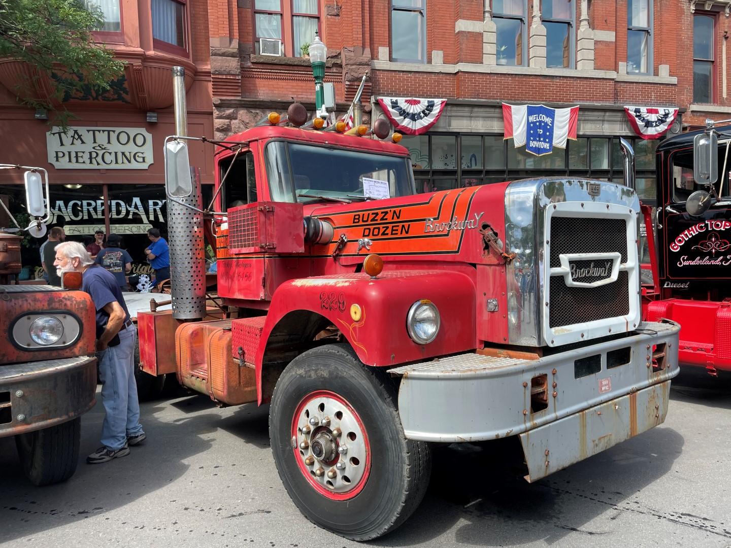
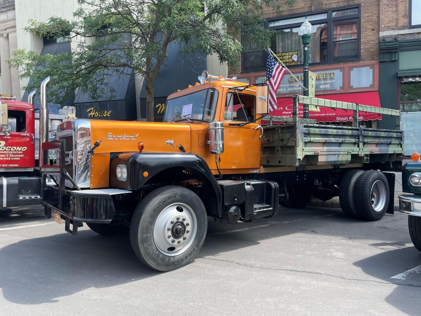
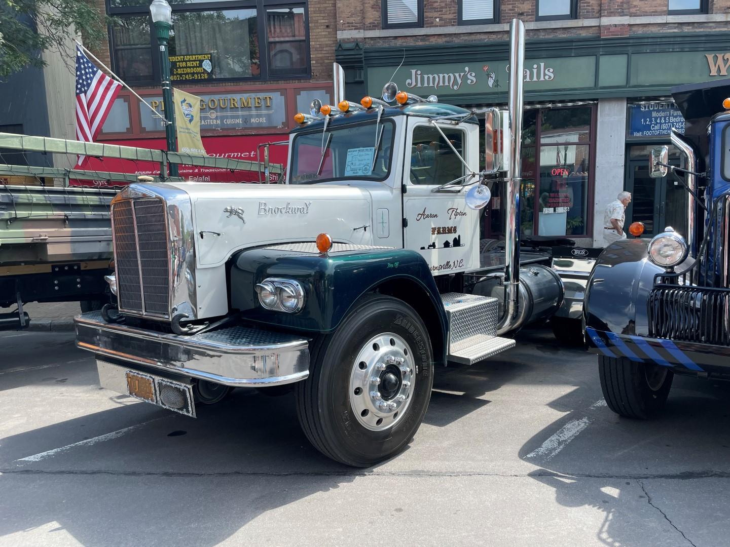
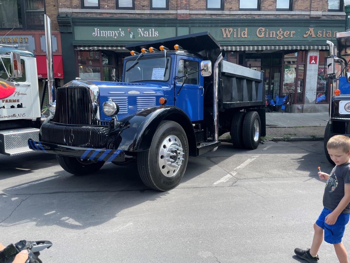
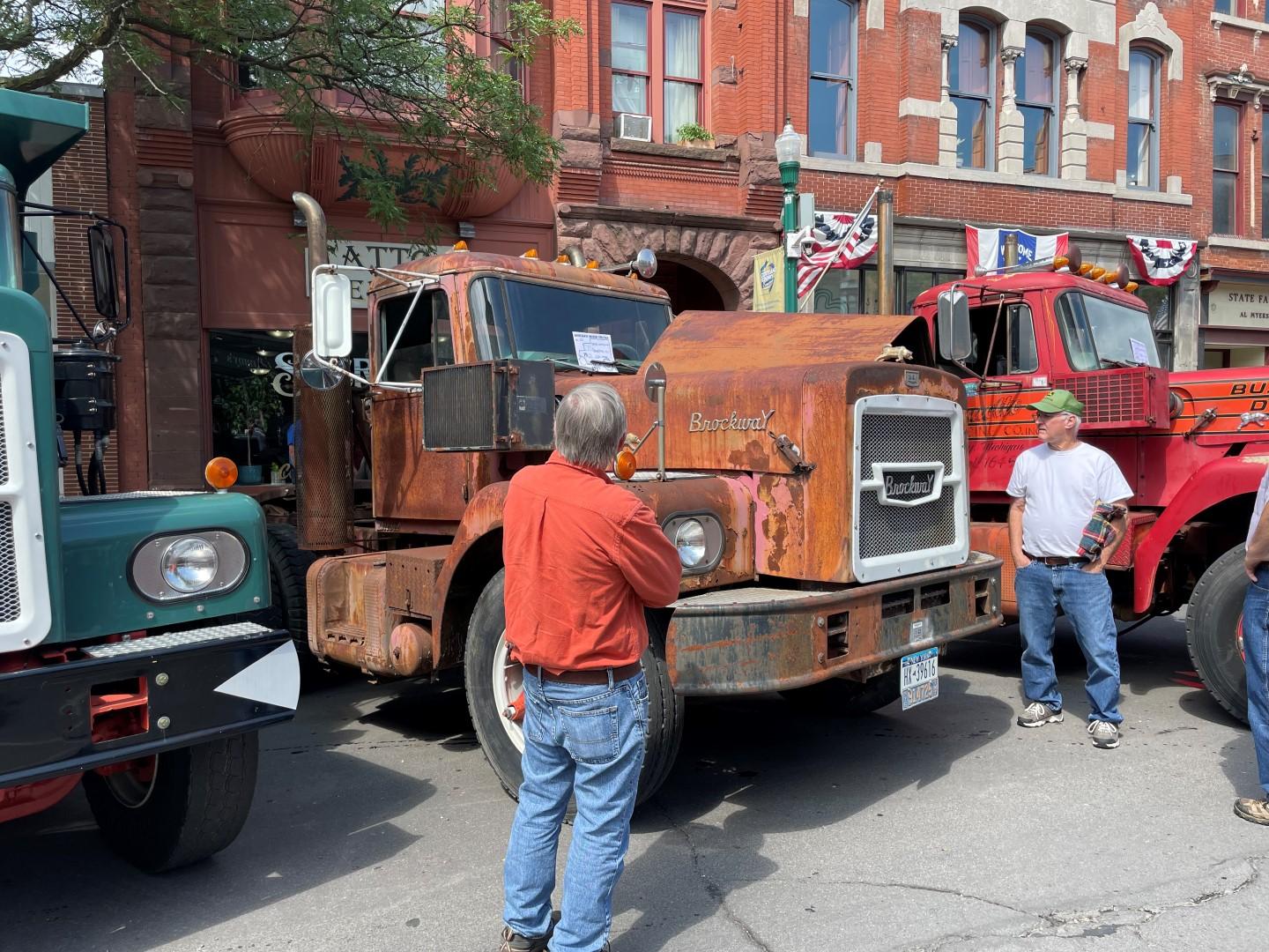
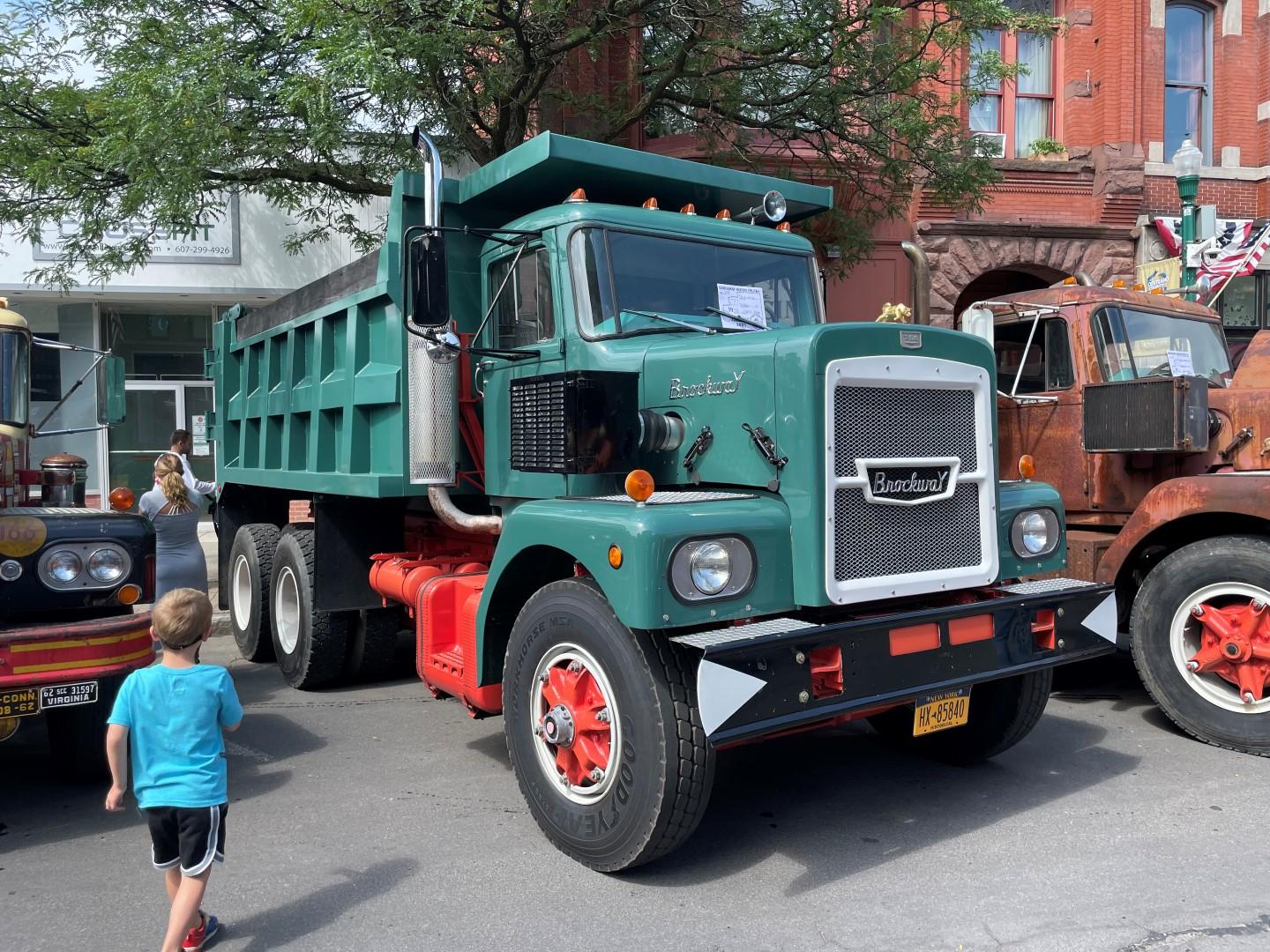
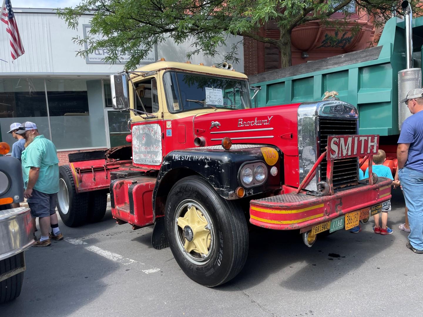
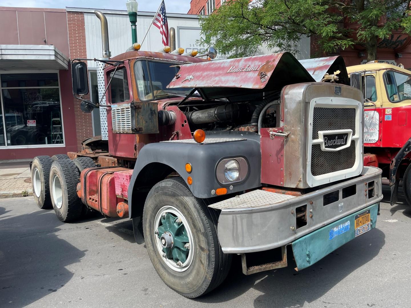
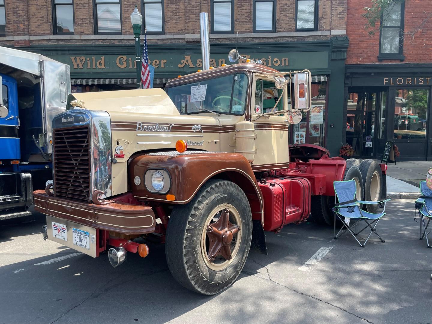
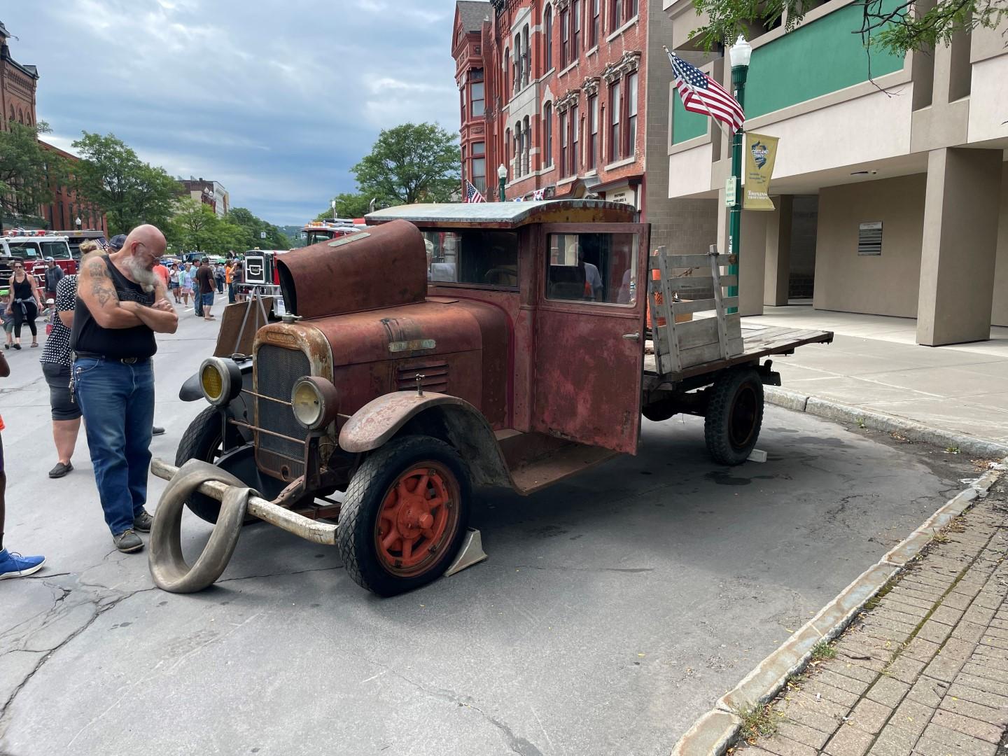
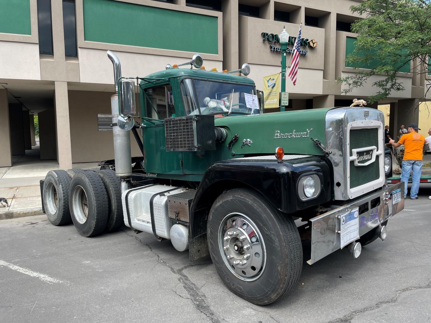
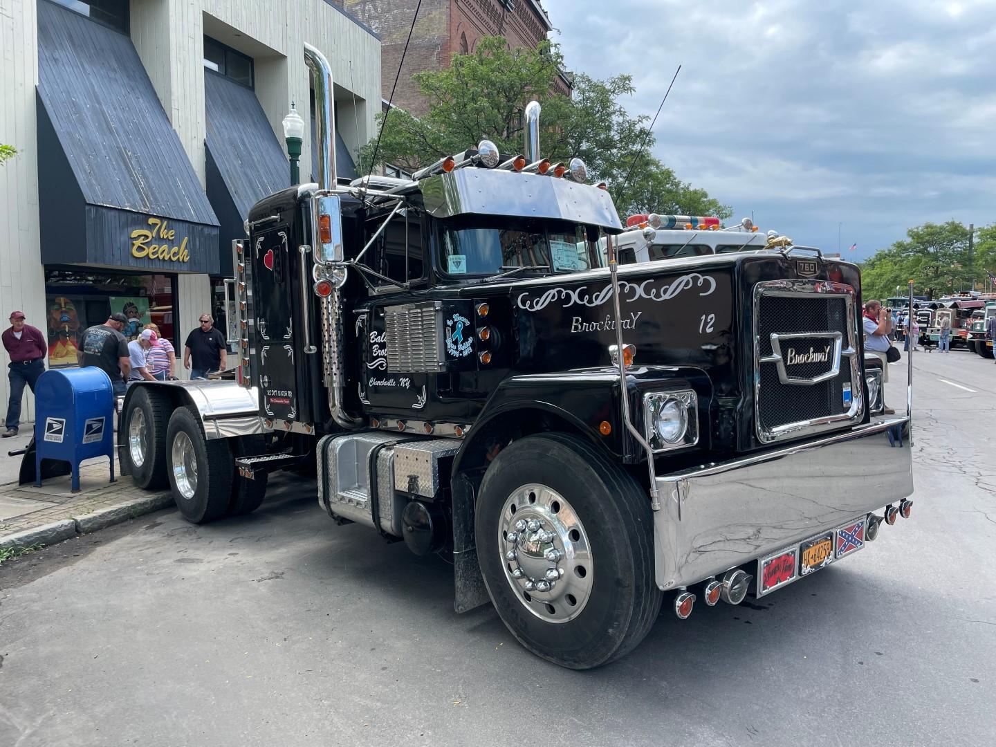
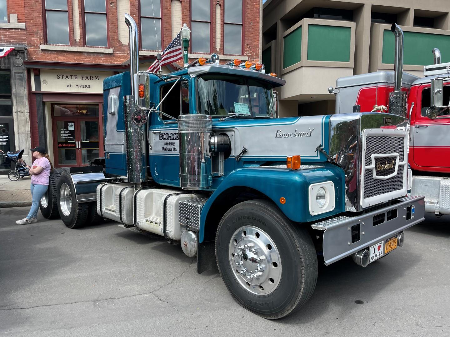
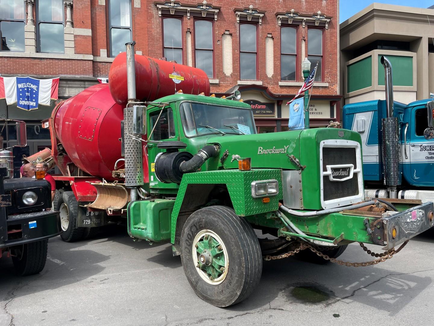
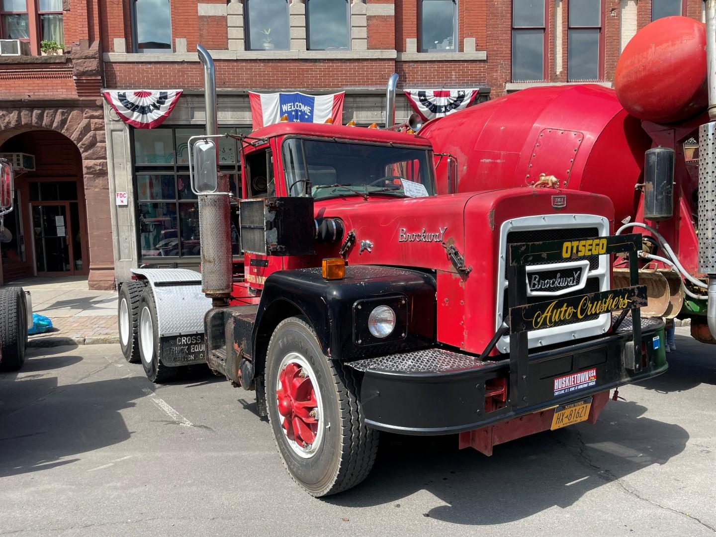
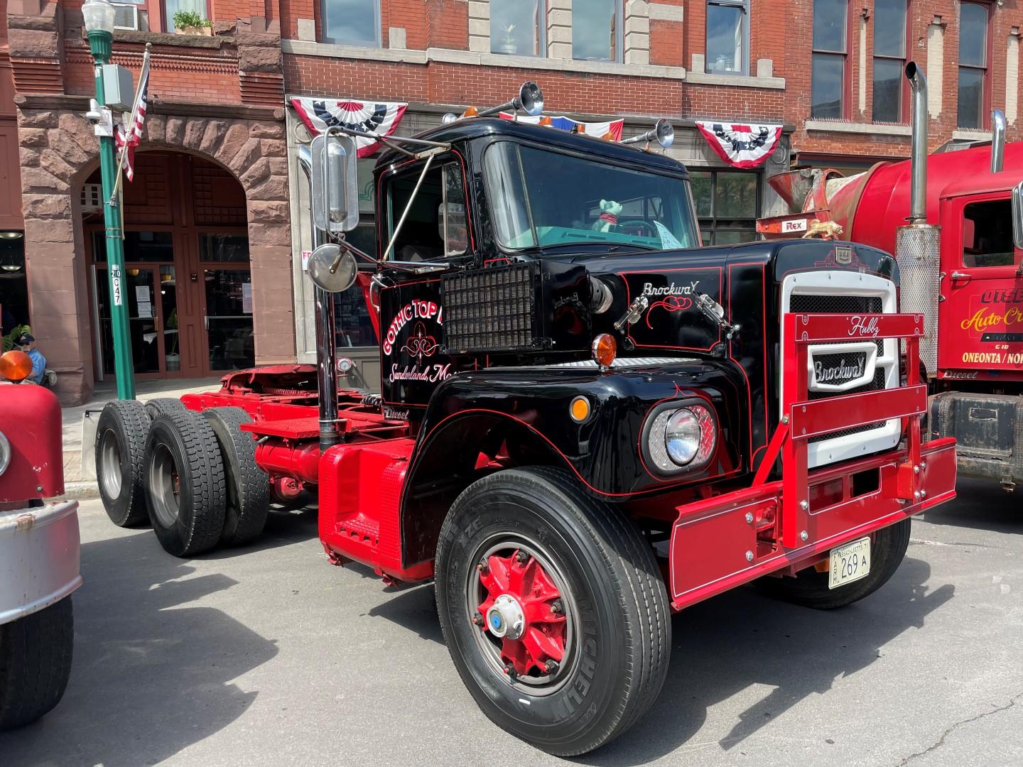
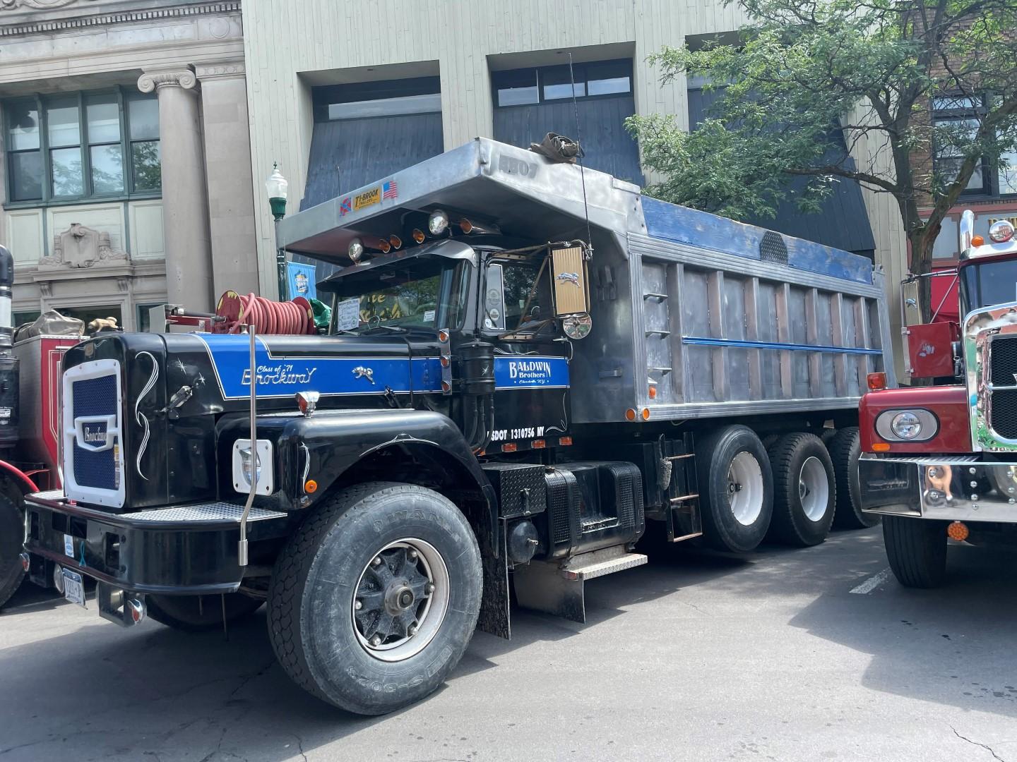
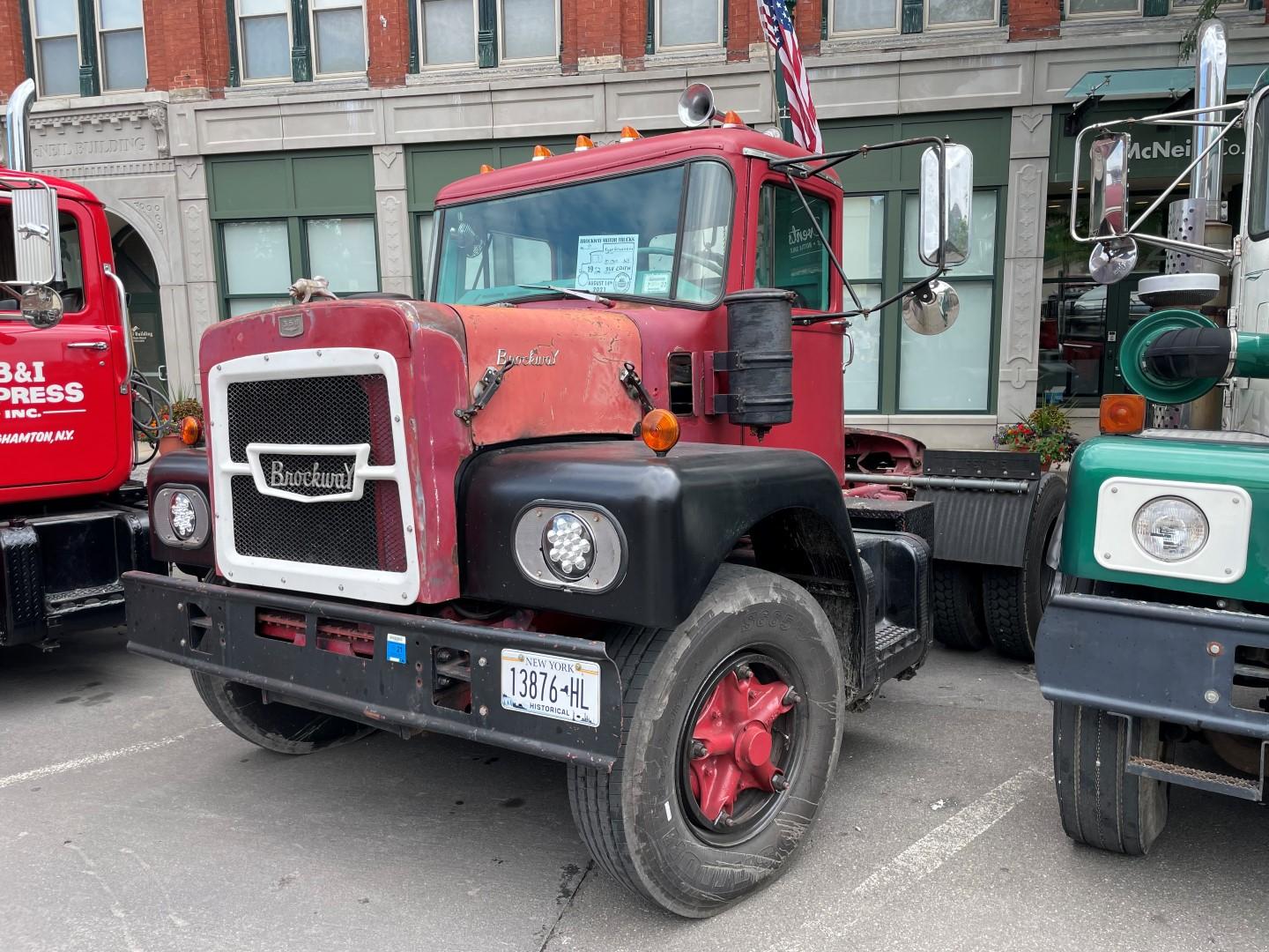
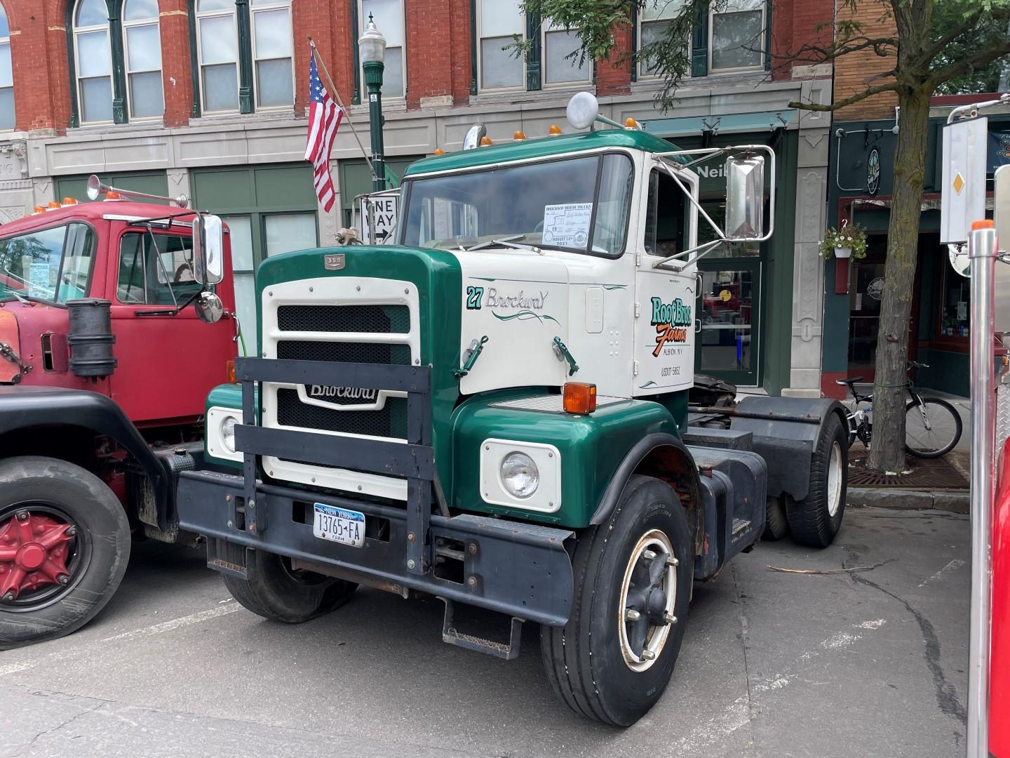
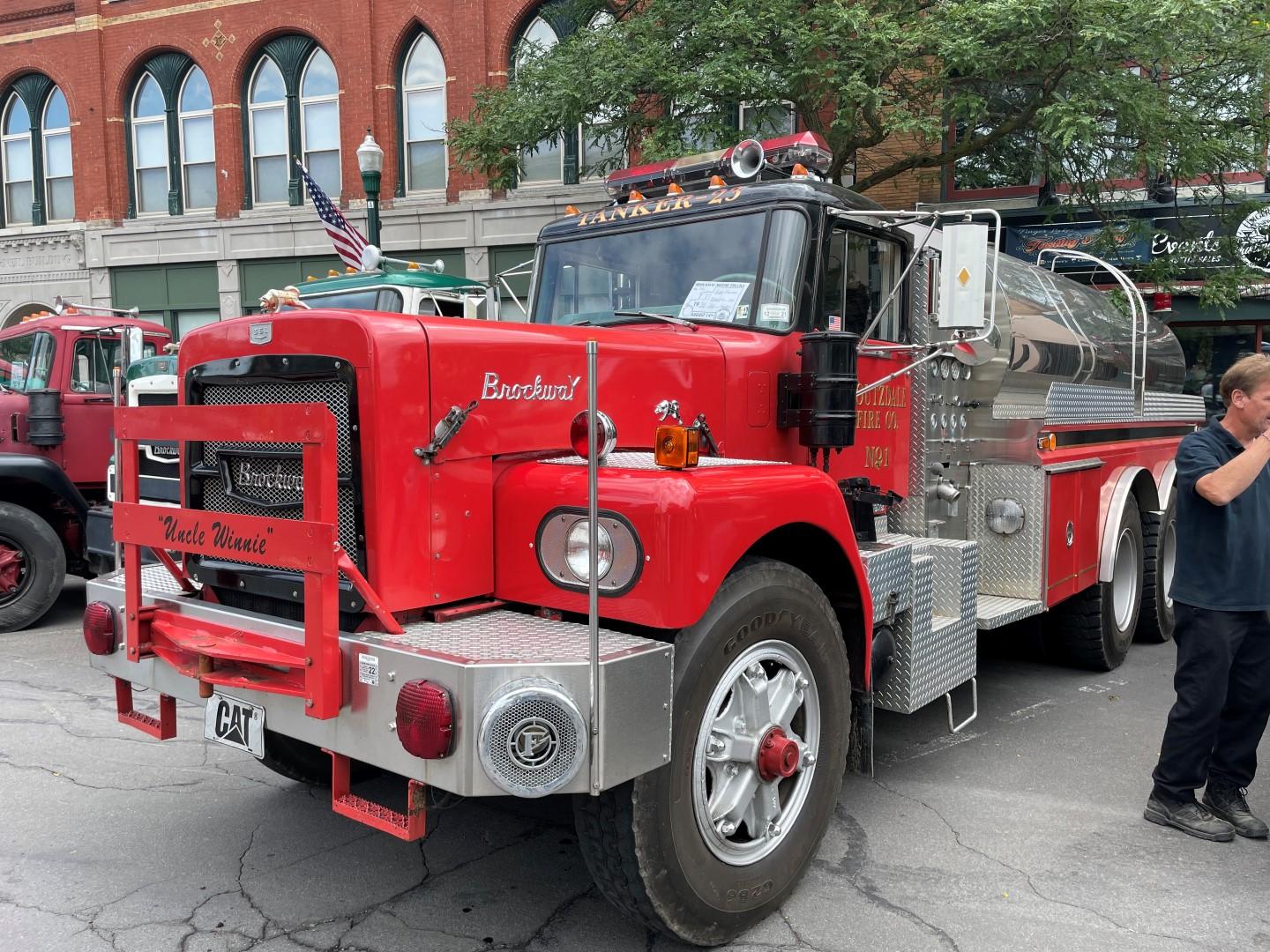
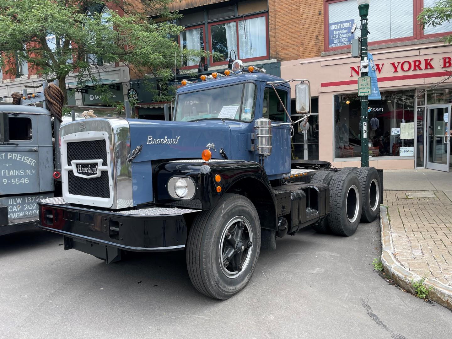
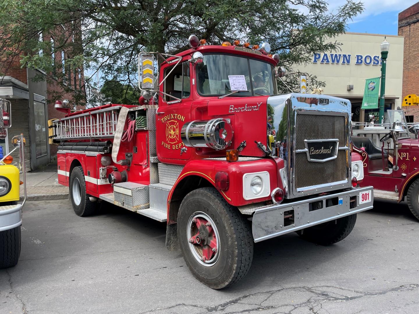
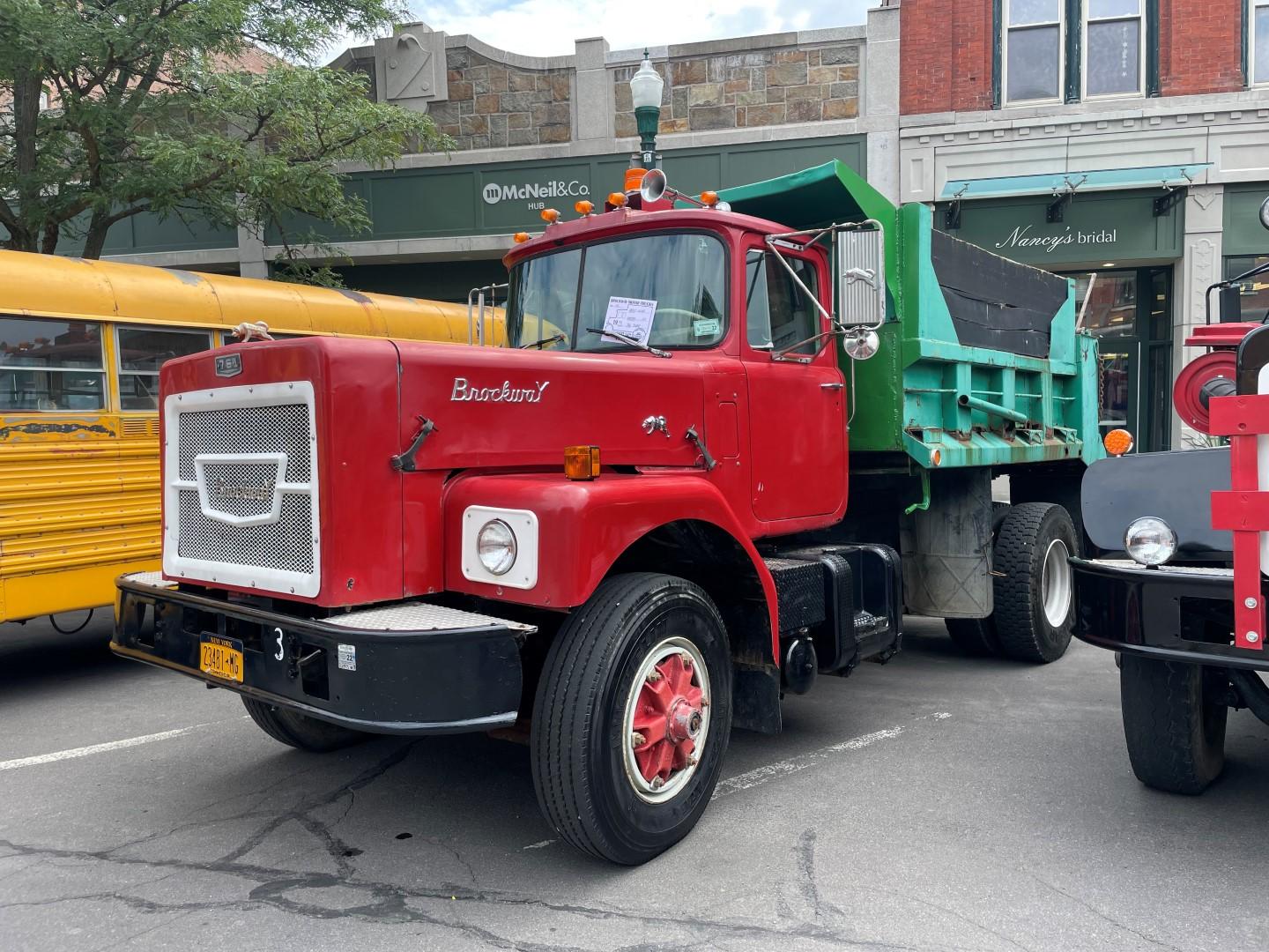
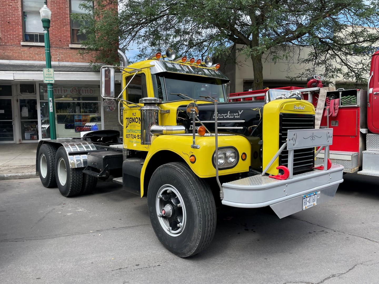
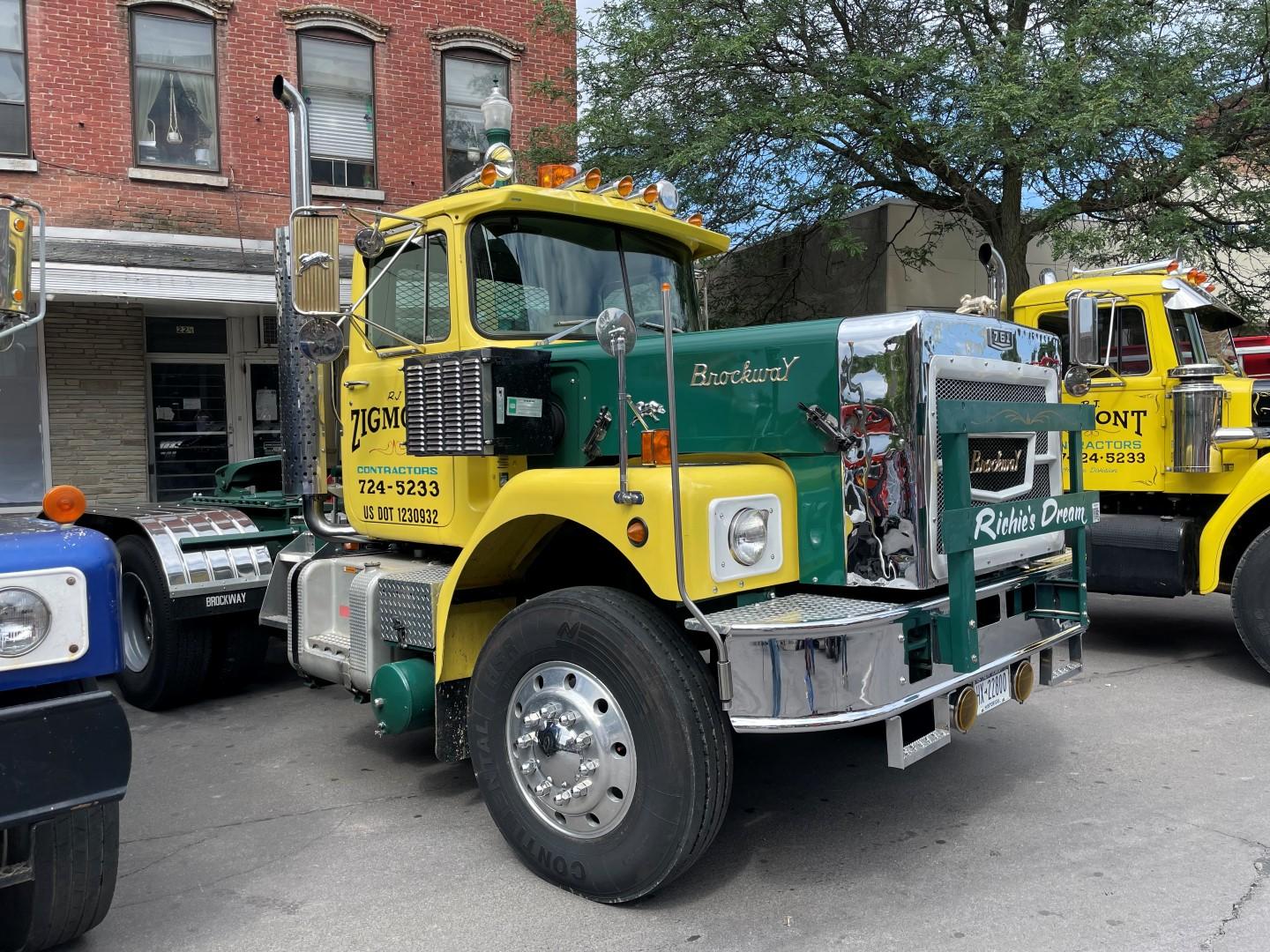
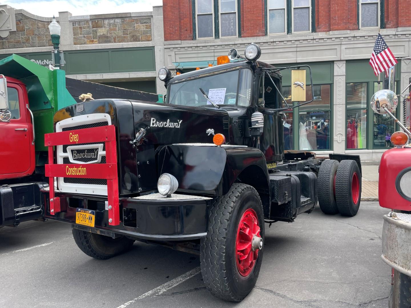
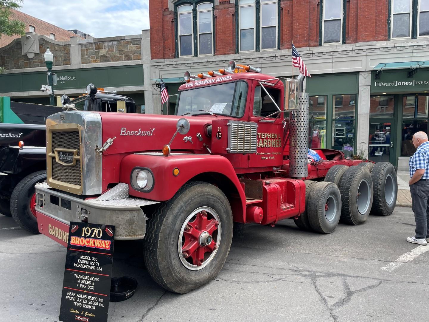
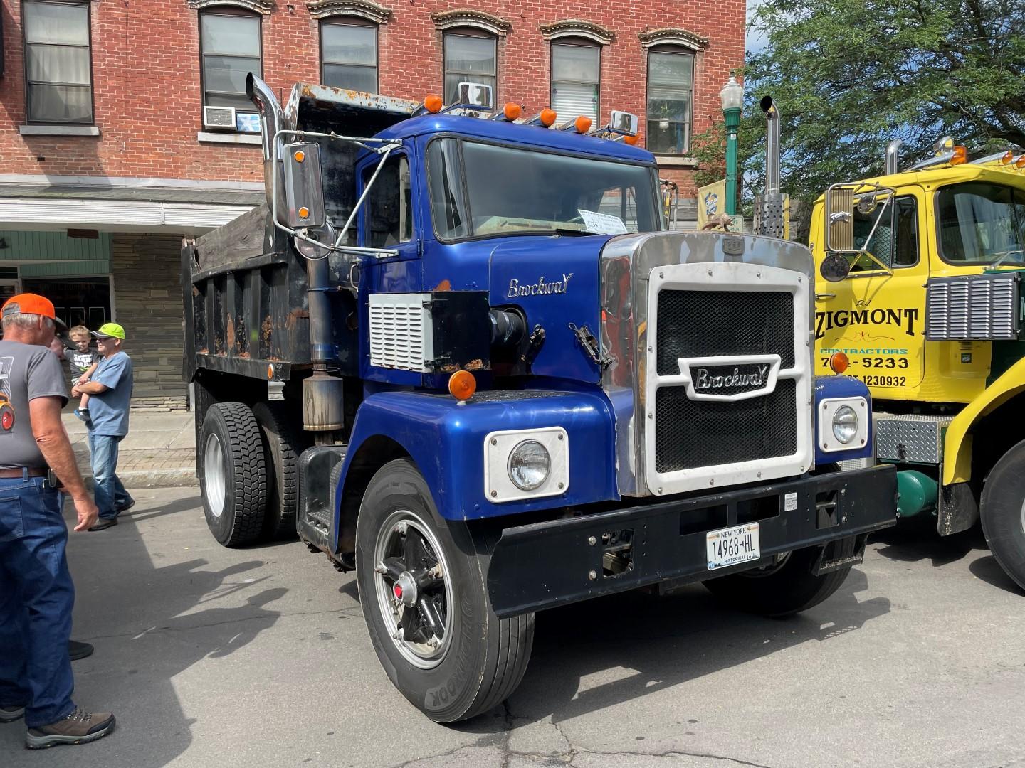
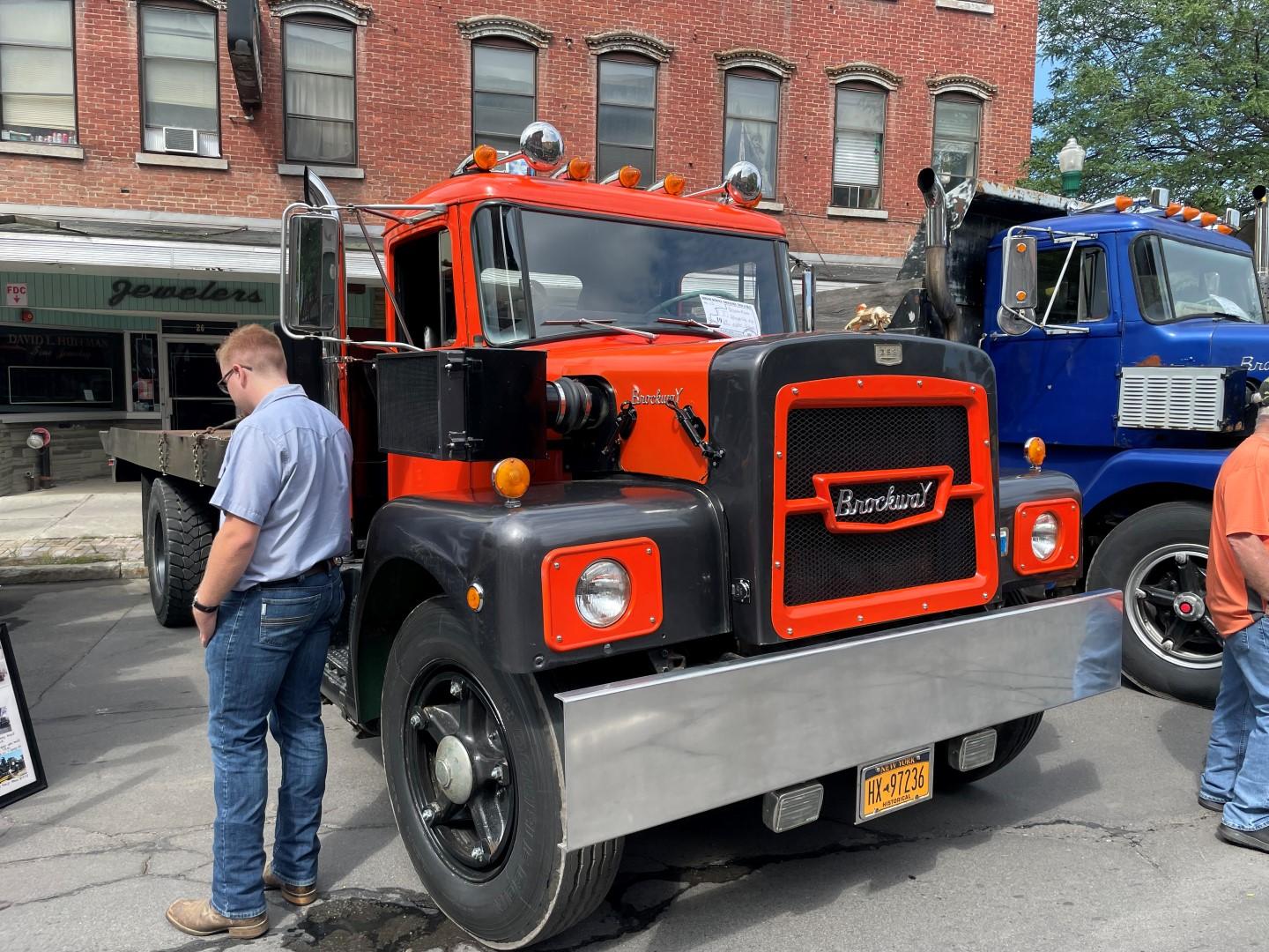
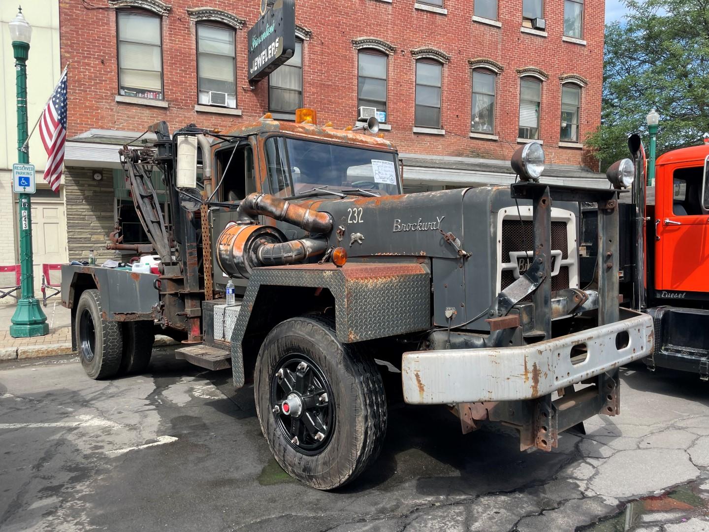
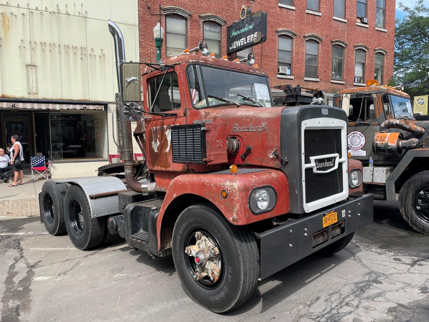
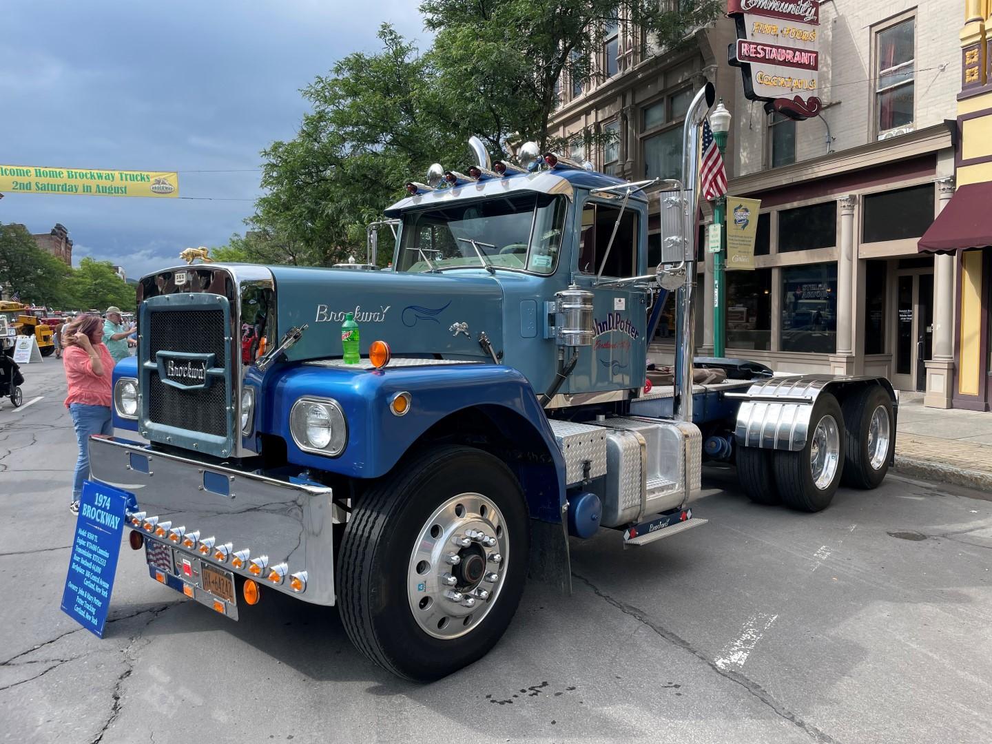
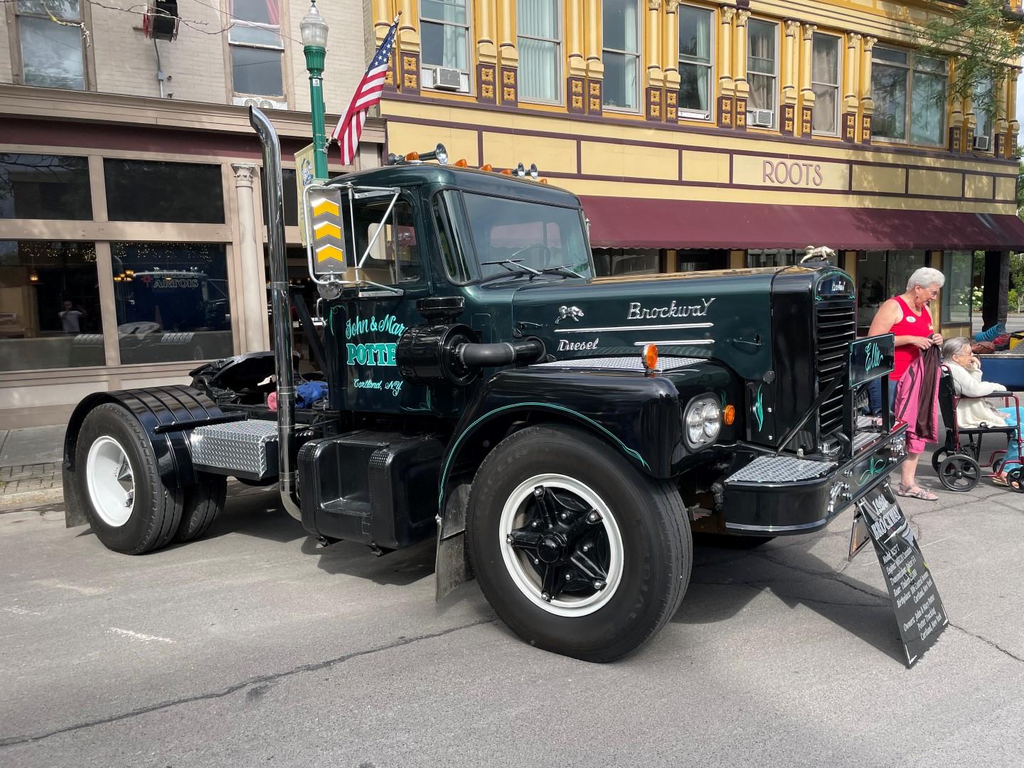
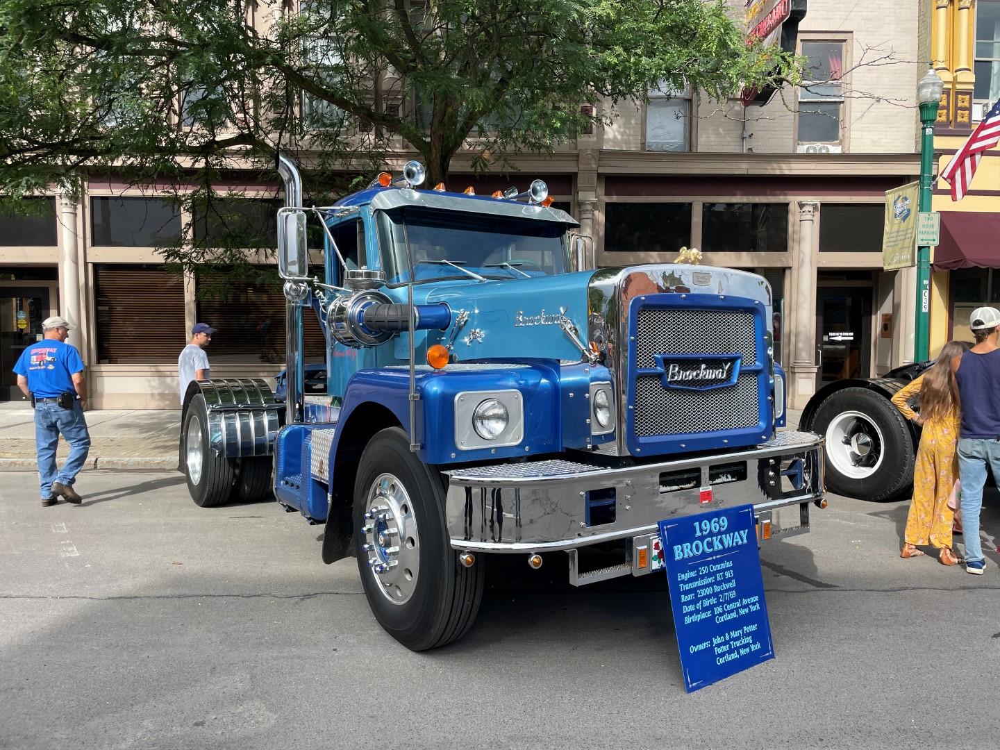
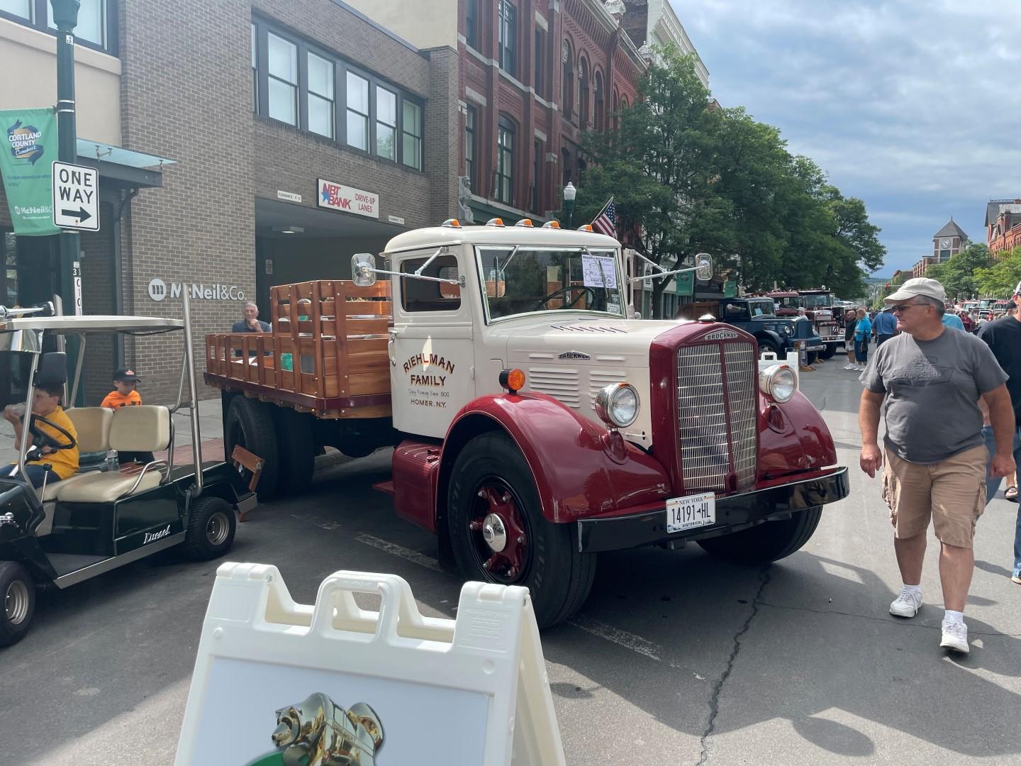
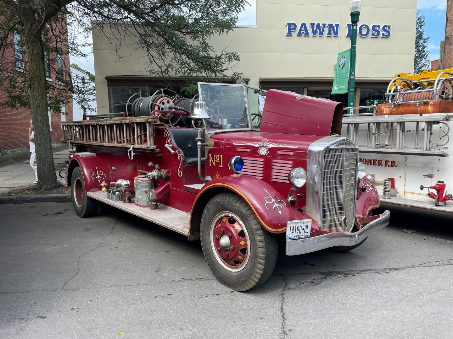
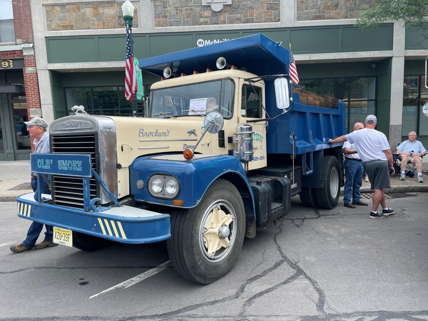
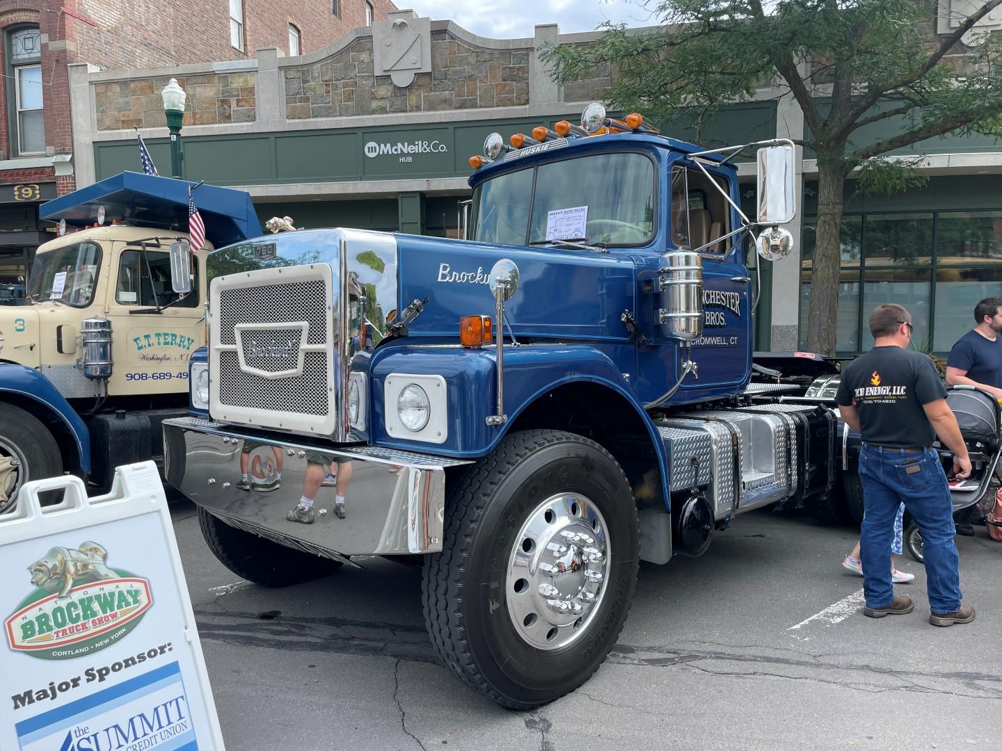
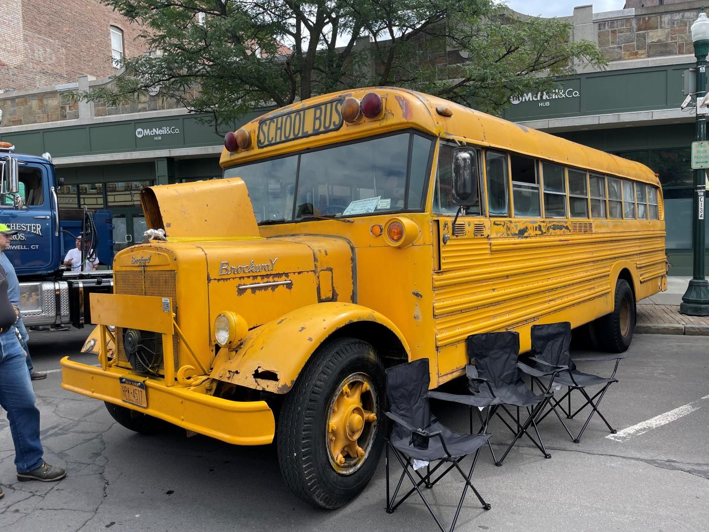
Hot off the press! Here are some pics of the 2021 Brockway Show in Cortland, NY!


-
There was one other thing I needed to do that I realized the summer before. For some reason there was no clutch switch installed for the engine brake. I did buy a switch for this but forgot I used it on the 155W for the 5.9 Cummins exhaust brake. I wound up ordering another one from PacBrake and it’s the exact same switch that Jacobs uses. Notice the diode on the switch that connects one terminal to ground. This is used to prevent the contacts from arcing within the switch... With the driver side fender off, this was the perfect time to install the switch. And it turns out the bracket that came with the switch worked out well also. It mounted the switch far enough off of the floor for the clutch pedal to activate it... By that time the powder coater texted me to let me know the parts were done so I went and picked everything up... And almost immediately I started to install everything, with the help of Maddie as well!!! Once the reservoir was mounted to the block I dug out the new filter I bought (from Amazon of all places... Fleetguard LF637 Power Steering Reservoir Filter) and the hardware for inside the reservoir... Once I installed the filter I made a new lanyard for the expansion plug using some stainless air craft cable I had that was left over from suspended light fixtures... And that’s about it for now...
-
Once I was done with both the oil and power steering pumps, I decided to install both of them since I was still waiting on the parts from the powder coater. I started with removing the original oil pump (which of course didn’t have the provisions for the power steering pump...) And then I set and bolted the new one in place... Then I installed the coupler that connects the splined shaft of the oil pump to the splined shaft of the power steering pump, Cummins parts #199589... And then I set the power steering pump in place... But I did learn a few things... first, the 3/8” mounting bolt closest to the inside of the block is almost impossible to get started with your fingers. So I decided to replace the bolts with 3/8” studs. It was a lot easier to start the nut on the stud. Second, the 1 1/4" cast 90 degree fitting needs to be installed and tightened before the power steering pump is installed. Once I was happy with the pumps I decided to replace the fuel line between the pump and the rear of the block. This line was replaced before but it wound up hitting the power steering reservoir bracket. You can see the old line here... I decided to bend a new one from 3/16” fuel line from Napa. I usually do pretty well bending these lines but for some reason I wound up doing this 3 times... In other words I take my time, measure everything twice, double check the direction of the bends etc, but hey, stuff happens. I should also note that I had to remove the center section of the floor to get to the fittings at the rear of the block. Fortunately this section of floor was in great shape and all the bolts had Never Seez on them, so they came out easy. On my third try I wound up with this... also notice the bracket I made with a cushion clamp towards the rear of the block. I have a big cam 350 sitting in the garage and noticed all the supports for the fuel so I realized I really needed to add one here... In the meantime Russ came up to the garage to drink some coffee and visit, and see how things were going with Ole Shepp. Fortunately I received his seal of approval on the power steering upgrade More to follow...
-
Hi mowerman... I'm sure it's a 1968. The serial number falls between 68200 and 68999 (based on my list). I also have a copy of the factory chassis record. It's just a coincidence that the serial number starts with 68. Brockway introduced the 300 series in the mid 60's and the earliest one I have on file is a 1965, and I believe the 360's came out in 1968. The early (early 1968) 360's had (4) headlights but by the time mine came out they went with (2) headlights.
-
Then I moved onto the power steering pump. The original pump I had was a Vickers V20F. For some reason the input splines were wore a bit so I decided to see about replacing the input shaft... At first I looked for a replacement shaft but realized they cost about $75 or so. Then with nothing more than luck I found a complete pump for sale on eBay that was rebuilt. Here why I say it was luck... They make about a thousand different variations of these pumps for every type of use. The one I needed was V20F 1P8P 38C 6F 11. I found this info from Eaton (Vickers) online and it explains how to break down the numbers... And the pump I found on eBay was the exact same number but 6E instead of 6F. In other words the only difference was that the it was rated at 6 gpm @ 1250psi instead of 6 gpm at 1500 psi. I was able to buy the pump for a little more than the cost of the replacement shaft (shipped!!!) so it was a great deal... Notice the arrows on the middle section of the pump. Stan A explained this was the direction of flow. Even if the new pump was backwards you can take it apart and flip it 180 degrees. So now I decided to remove the pressure regulator valve from the old pump and put it in the new pump, in order to increase the pressure from 1250 to 1500. And it’s a good thing I did, I found out that the small spring within the valve was broke... In the previous pic you can also see 3 shims. I also disassembled the new pump and it only had 1 shim. According to the Vickers literature, you raise the pressure by adding shims and reduce the pressure by removing shims. I wound up using the new pump body along with the input shaft and used the original (3) shims to maintain 1500psi. Here is a better pic of the old and new input shafts... Once I was done reassembling the pump I also gave it a coat of Cummins beige... That’s it for now!


.JPG.1d91e8367899aa30bde5a04f8d828b3b.JPG)


BMT Forum Logo
