


Geoff Weeks
-
Posts
2,609 -
Joined
-
Last visited
-
Days Won
7
Geoff Weeks's Achievements
")


-
Mack B873sx restoration
Geoff Weeks replied to hicrop10's topic in Antique and Classic Mack Trucks General Discussion
I can mail it to you, but do you have the pulley behind the damper to drive it off of? is the block drilled for the mount? I know all Big Cams have whats needed , but not sure on the early stuff. I'll pull it off and put it in a box, PM me with the address. Yours for the postage. -
My '48 Int. KB-7 (Sanford)
Geoff Weeks replied to Joey Mack's topic in Antique and Classic Mack Trucks General Discussion
Yes, I would have to agree it is night and day. I could search out parts for my 30-40 year old tractors while on the road, and by the time I was home the parts were there waiting to be installed. Imagine before the internet going to a parts house and asking for the rubber gasket (or spool valve) for a Bendix MV-2 multi function valve. Getting a blank stare from the counter person. "We sell new ones", for a $13 part. Today the manuals are on line in .pdf form and the part numbers are listed so you can do a parts search for someone who has the part. I had an easier time getting parts for the same truck when it was 30 years old then I did when it was 6 years old, while that doesn't make any sense, it is the truth. I once got a complete set of 6 rebuilt injectors sealed in shipping box for $156 for the whole set, no core charge! I'd pick up gasket sets for pennys (remember those?) and throw them in a drawer, after a while I had several complete or mostly complete sets to use as needed. -
Mack B873sx restoration
Geoff Weeks replied to hicrop10's topic in Antique and Classic Mack Trucks General Discussion
A word to the wise, make the mount 2x-3x more stout then you think it needs to be. Delco recommends 3/8" plate for making mounts. I found that it needs to be at least that thick and firmly mounted to the engine to prevent it from breaking. As I stated earlier, you can keep that rebuilt generator as is and it will do the job just fine. -
Mack B873sx restoration
Geoff Weeks replied to hicrop10's topic in Antique and Classic Mack Trucks General Discussion
Ok, I am mixing up two people with old Red Macks with Cummins in them! I have Big Cam mounts that are yours for the postage but don't think it will work with your set-up
-
Mack B873sx restoration
Geoff Weeks replied to hicrop10's topic in Antique and Classic Mack Trucks General Discussion
I might have a Big Cam alternator mount. what does your big cam have on the front of the engine. Big Cam 3 should have duel belt sheeves behind the damper for alternator drive. am I mixing you up with another guy who has a Big Cam 3 and you have an old Cummins? -
Positive Ground - Alternator Connection
Geoff Weeks replied to 56LT's topic in Electrical, Electronics and Lighting
https://www.shopzorkos.com/Category/5116T this is close to what I had. The one I had bolted directly to the back of the alternator, this one is remote. -
Mack B873sx restoration
Geoff Weeks replied to hicrop10's topic in Antique and Classic Mack Trucks General Discussion
Those large case generators aren't that common anymore, and in my mind are of value. I have 2 12 volt and 1 6 volt so don't need more. If it were I, I'd keep the generator (period correct and 50 amps is plenty) as it will work just as well on either polarity. But that is just me. -
Positive Ground - Alternator Connection
Geoff Weeks replied to 56LT's topic in Electrical, Electronics and Lighting
yes. Both Delco and Leece Neville used to make duel output alternators that would allow you to eliminate the Series/Parallel and keep 24 volt cranking and 12 volt for everything else. The Delco is still available (Delco 30SI-TR) but I only see it in negative ground. 40 years ago I had the part to convert that JB2500 to the same, but it is long gone. I haven't seen the JB kit since I had the one I had. Series parallel seams to "throw" people as bad or worse than positive ground. https://smithcoelectric.com/products/240-821-new-alternator-for-delco-30si-12v-90a-with-24v-transformer -
Positive Ground - Alternator Connection
Geoff Weeks replied to 56LT's topic in Electrical, Electronics and Lighting
You are 100% correct the case is neutral on the JB series. so the positive goes to the frame on a + ground truck and the negative goes to the truck wiring. The internal voltage regulator doesn't care as it is isolated from the alternator frame and gets its power from the + and - stud on the alternator itself. -
My '48 Int. KB-7 (Sanford)
Geoff Weeks replied to Joey Mack's topic in Antique and Classic Mack Trucks General Discussion
BTW is Dennis Kirk gone? I have a few of the older catalogs but haven't tried to find them on the web. -
My '48 Int. KB-7 (Sanford)
Geoff Weeks replied to Joey Mack's topic in Antique and Classic Mack Trucks General Discussion
But think of the enjoyment reading those catalogs and dreaming about what we would get when we had enough coin saved! In some ways looking for parts for these older trucks is as much a treasure hunt as it was in the old days sending off and waiting for weeks for the parts to come. -
My '48 Int. KB-7 (Sanford)
Geoff Weeks replied to Joey Mack's topic in Antique and Classic Mack Trucks General Discussion
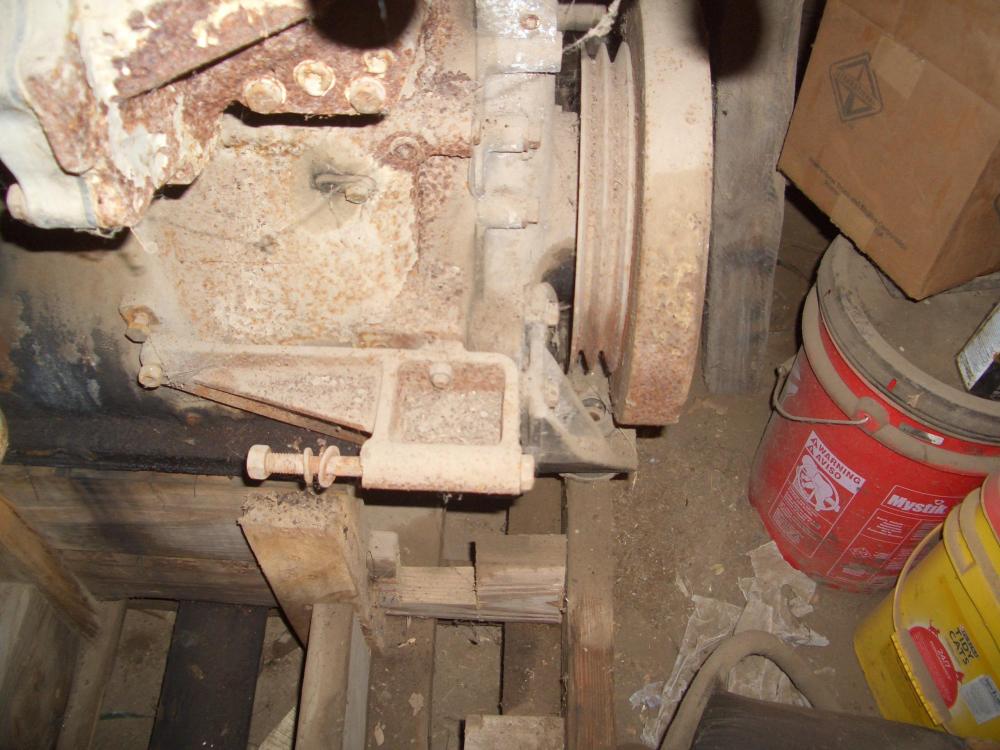
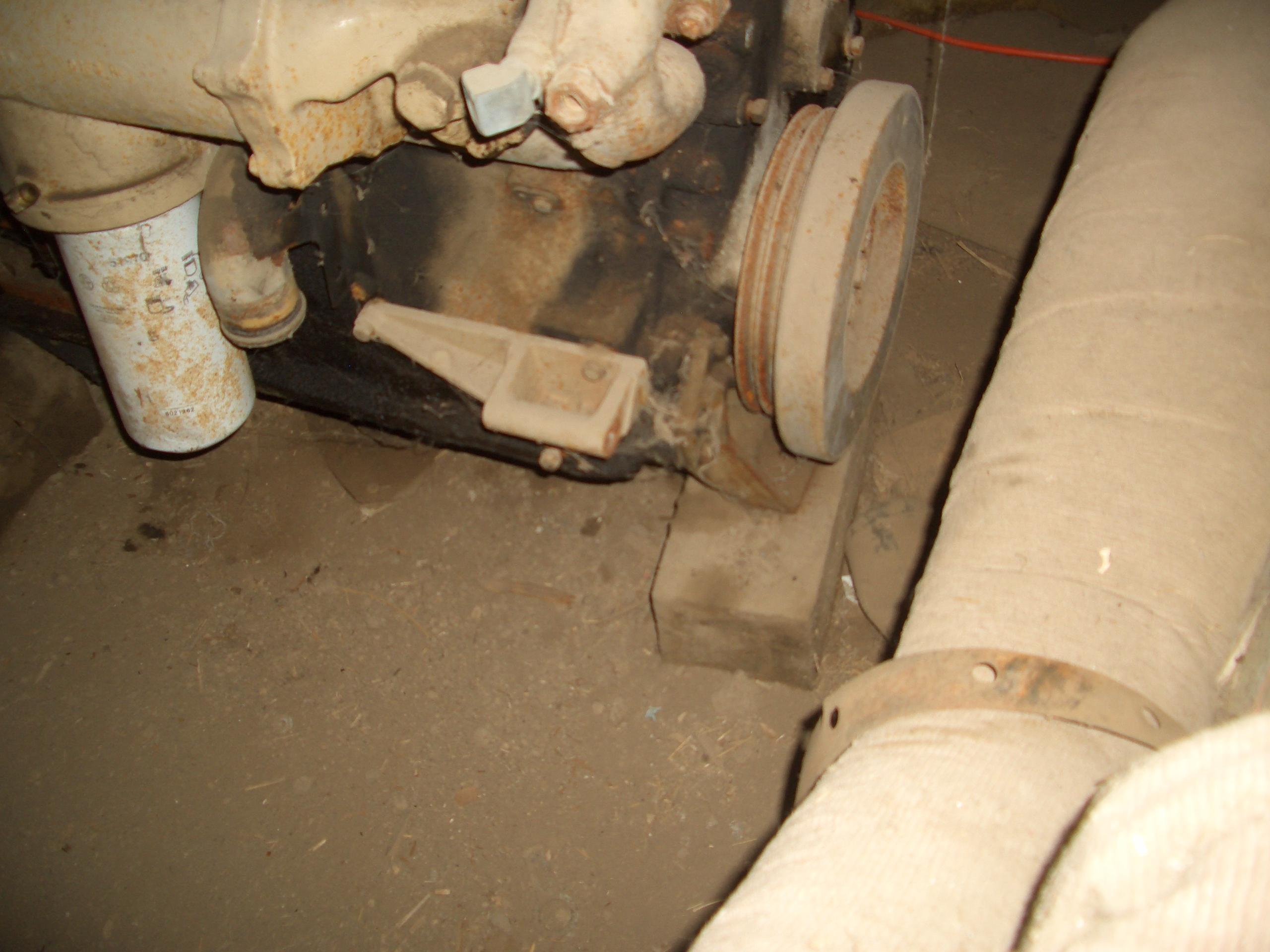
Thank-you but I am just passing on what I learned with my own truck. Might be worth throwing some plastic gauge on the bearing while the pan is down. Bearings show up every once an a great while on E pay. The mains seam harder to find then the rods for some reason. If yours are ok but on the high side, better to have time to find them. I think Egge can supply them, or could but they are proud of them, for sure. -
My '48 Int. KB-7 (Sanford)
Geoff Weeks replied to Joey Mack's topic in Antique and Classic Mack Trucks General Discussion
Let us know how it turns out. I will freely admit I have more to learn on motors and how the current flows in them. simple 2 pole generators or motors it really only can have one flow path. I am less sure when it comes to 4 pole esp with how the windings are on the armature. -
My '48 Int. KB-7 (Sanford)
Geoff Weeks replied to Joey Mack's topic in Antique and Classic Mack Trucks General Discussion
Unless it has been rebuilt, that is 80 years of accumulation in there. Likely most of it with non-detergent oil, which allows the heavy stuff to settle out. -
My '48 Int. KB-7 (Sanford)
Geoff Weeks replied to Joey Mack's topic in Antique and Classic Mack Trucks General Discussion
That light gauge wire is enough to balance any slight difference in the current through the paired coil path, but I don't think it is heavy enough to carry a full 1/2 of the current draw of the starter. Yes, mine have that wire also. I don't remember what gauge it is, something like 14 or maybe 12 at the most. Like I said, I don't know what is going with those coils, they are NOT the same as the stock set-up. I am just guessing here, but I wonder if for 12 volt they ran all the coils in series, but in that case there should be a large conductor tying the two "hot" brushes together, the same size as the series coil stock itself. That little wire can not carry that kind of current. All I can tell you for sure, is that is not how the stock motor is set-up. If you can, bolt the pan back up and run it for a few hours to flush more gunk out of the block, use RTV or the old gasket so you don't waste a new gasket until the final time the pan goes up. I was surprised by how much more stuff came out after the 1st cleaning.


BMT Forum Logo
