

paulbrook
-
Posts
123 -
Joined
-
Last visited
-
Days Won
3
Content Type
Profiles
Forums
Gallery
Events
Blogs
BMT Wiki
Collections
Store
Everything posted by paulbrook
-

AC Hood
paulbrook replied to paulbrook's topic in Antique and Classic Mack Trucks General Discussion
What I could really use if anyone has such a thing are close-up pictures of the two handles on the sided - the ones on my old hood are just some flat strip bent into a D shape and welded on, and also the sprung bonnet clips that hold the hood down, as I do not have those at all, or even the remains of them. -
AC Hood
paulbrook replied to paulbrook's topic in Antique and Classic Mack Trucks General Discussion
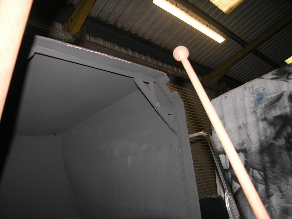
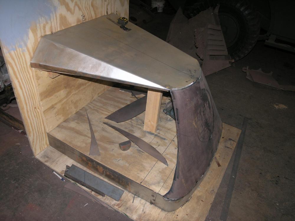
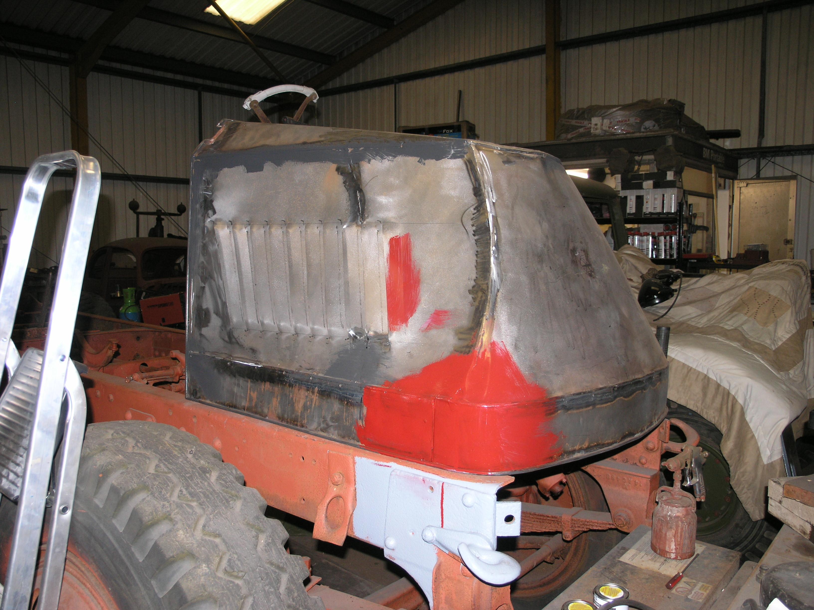
got the inner strengthening pieces in and thought that I had better just check the fit. Not too bad. Plenty still to do but it is looking good so far. Sorry about the daubs of paint. The black is a fantastic primer we use on bare steel, the red is a color my daughter thought it would look good in. I am less sure.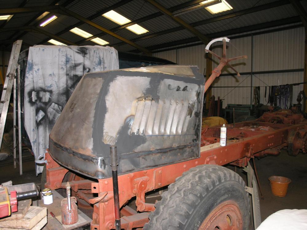

-
AC Hood
paulbrook replied to paulbrook's topic in Antique and Classic Mack Trucks General Discussion
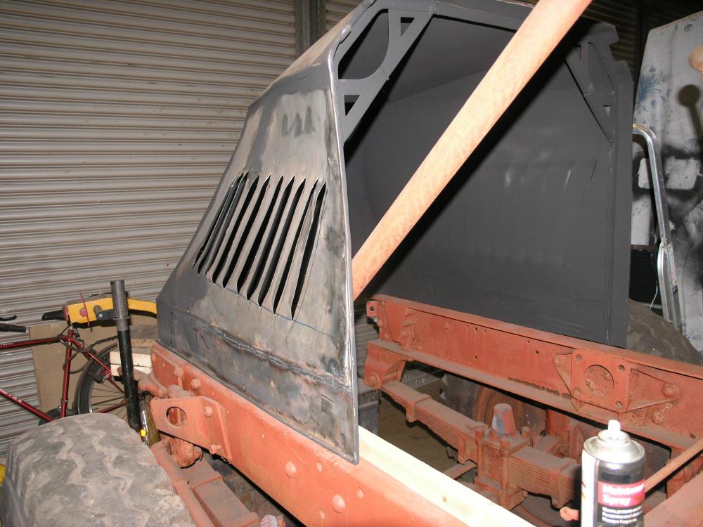
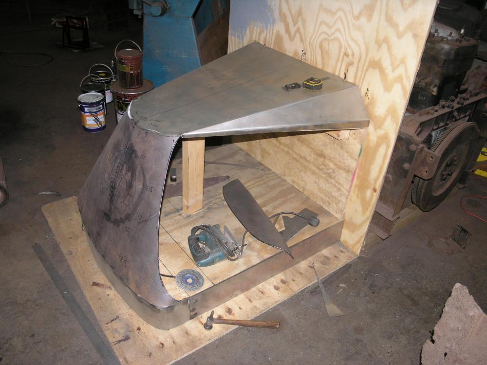
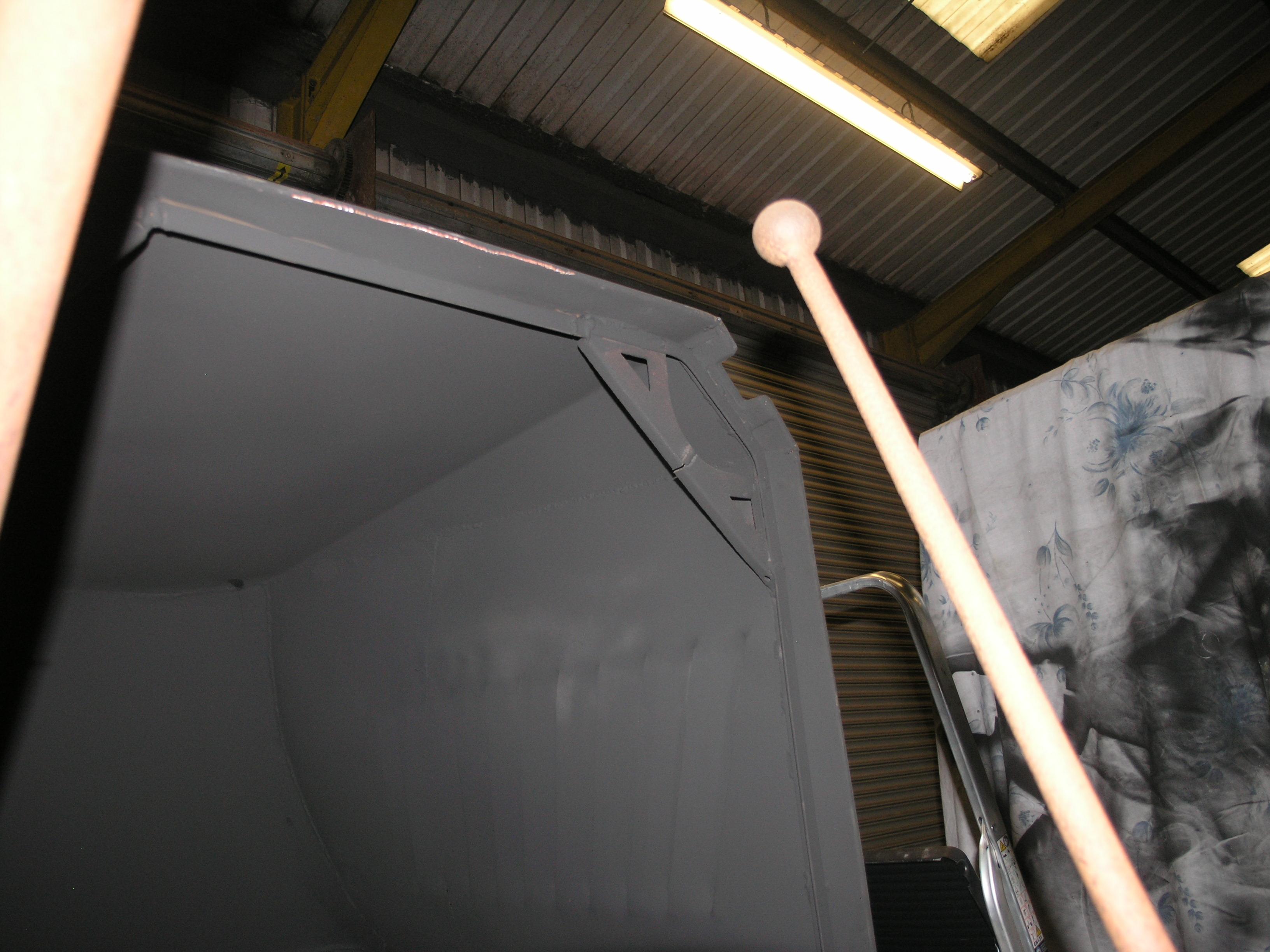
Side panels done. Seamed up at the front it should be a folded joint but I will add a strip on later that will look perfect. Then I will salvage the hinges etc from the original. For the rear and bottom wired edge |I intend to cheat and use solid rod welded continuously taking care not to add too much heat.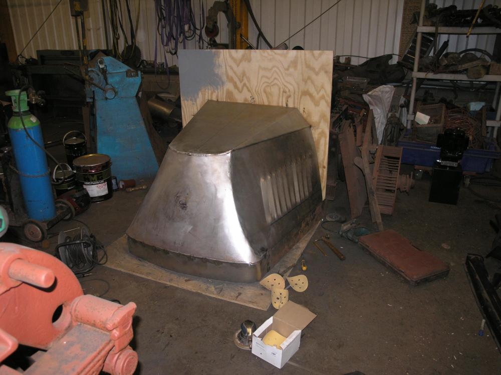


-
AC Hood
paulbrook replied to paulbrook's topic in Antique and Classic Mack Trucks General Discussion
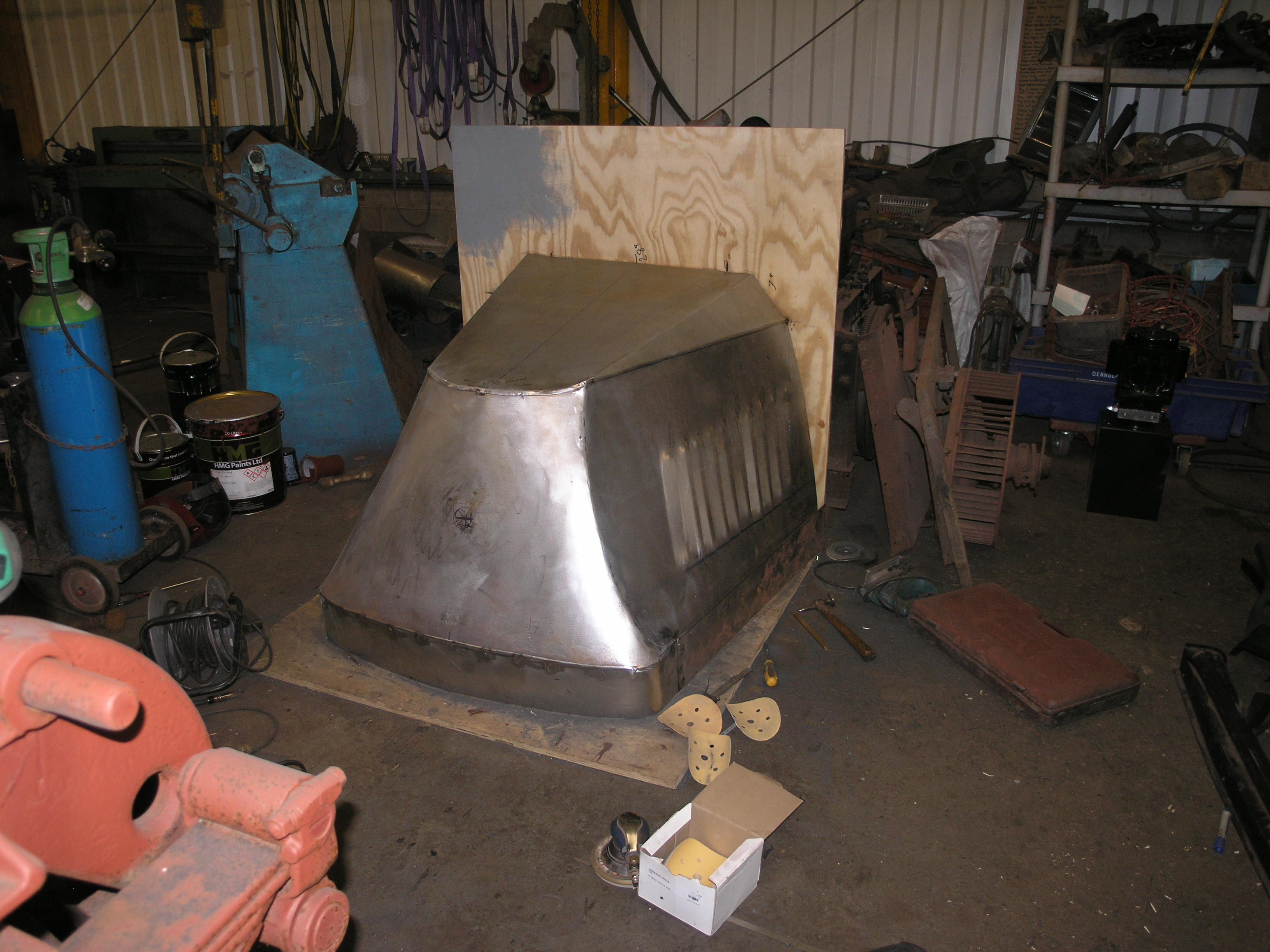
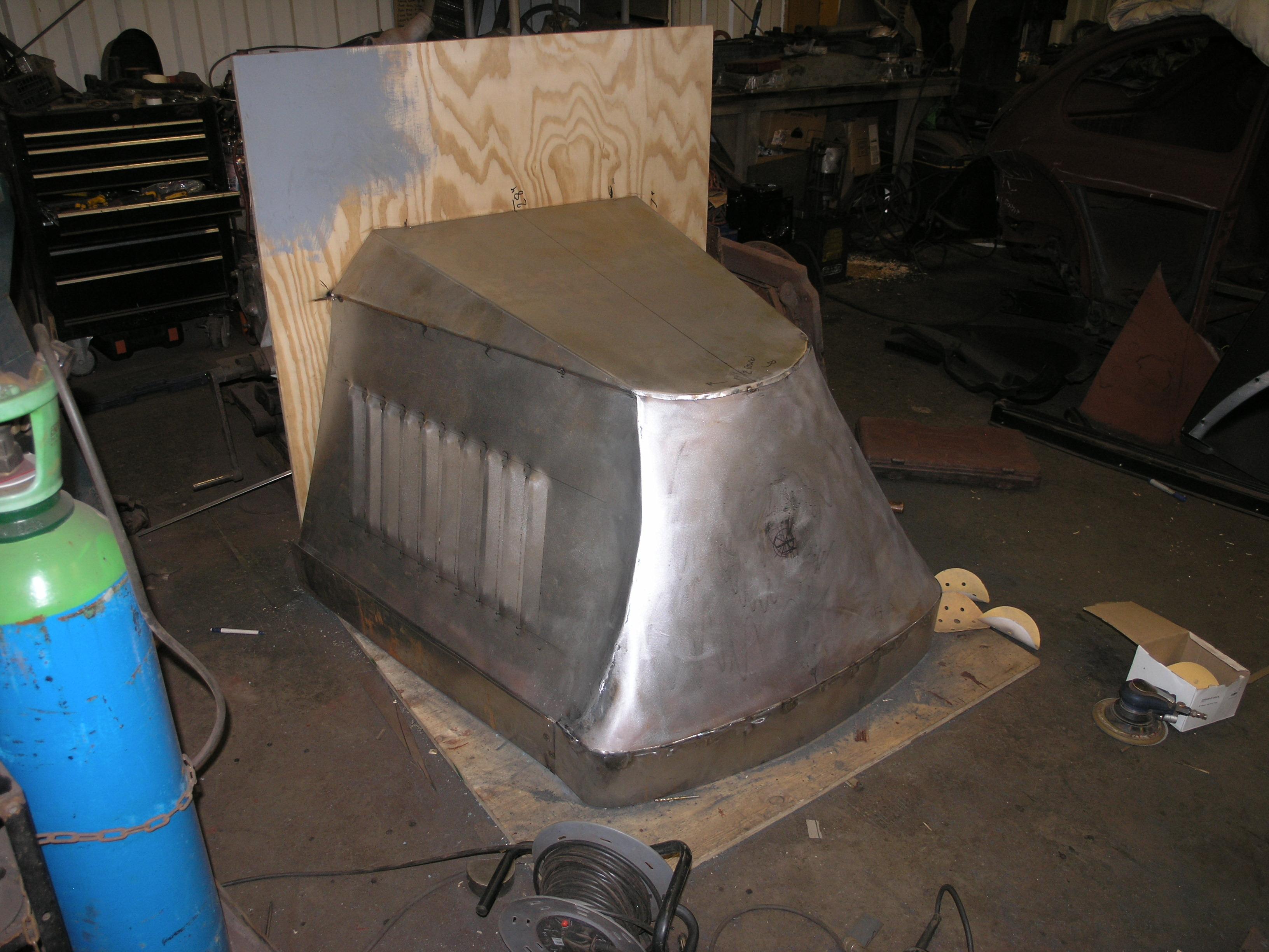
Sorry I tried and failed to upload these progress pics last week. Everything except the side panels with the louvers now done. I intend salvaging the whole emblem from the original front. Wish me luck putting louvers into curved side panels!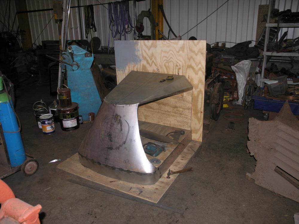
-
WANT TO BUY OR TRADE AC Mack radiator parts needed
paulbrook replied to redington's topic in Parts Wanted
I have only just caught up with this. We made don some lamp brackets. May he rest in peace. As for ACs if anyone has an early jug engine I know a 1917 truck in France that needs one!!! -
AC Hood
paulbrook replied to paulbrook's topic in Antique and Classic Mack Trucks General Discussion
Are you my dad? -
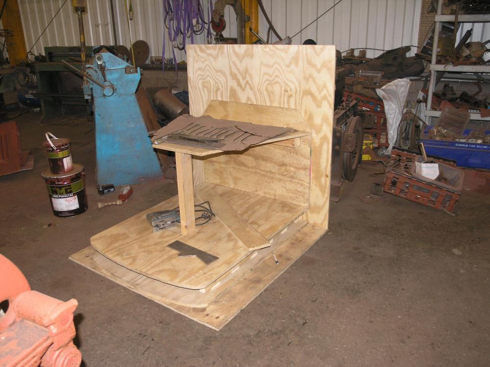
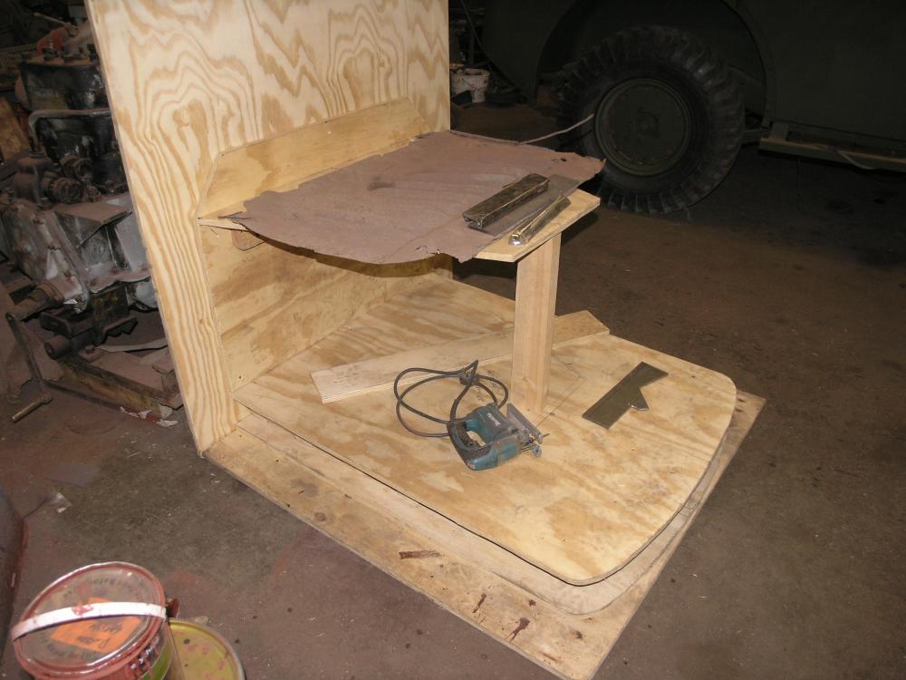
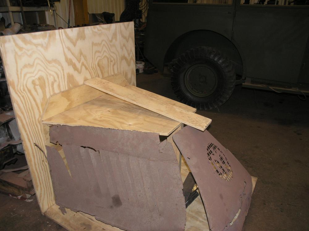
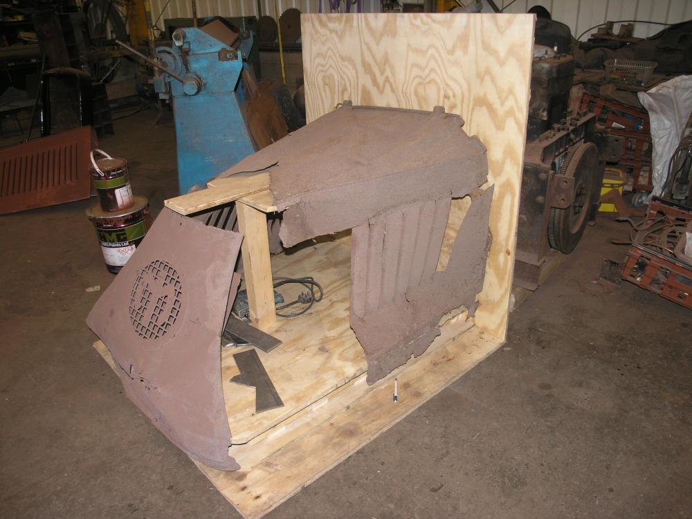
As some of you know I have a '29 AC. Anyway its time to think about the hood, which I am going to be working on over the coming days. This involves working from the original Mack drawings and making a "buck" into which each of the various component parts will be put as I make them. Also in there is the male former for the side louvres (louvers) - which is still work in progress as there is not enough clearance in either my big fly press or the hydraulic press to get the whole side piece in. I am also lucky in that I have the majority of fittings such as hinges and so on! I will add more pics as the work gets underway.

-
I honestly thought that the End of Days would be a bit more exciting than starving, alone, at home, wiping your ass with a sock.
-
Seam sealer and the like should be polyurethane not silicone. You are right about gasket sealer though as that seems to be silicone based, but applied in small quantities. What happens with using silicone (the household type) is that tiny flecks and smears disrupt paint applied later

-
Restoration of my 1929 AC
paulbrook replied to ekennedy21's topic in Antique and Classic Mack Trucks General Discussion
Brilliant and a great inspiration. Thanks for sharing! -
The other thing about silicone is that paint hates it, and any slight silicone residue will result in "fish eyes" in the paintwork which can be a PITA. If you do use silicone or suspect there could be some about then wipe down the primer coat with silicone removing panel wipe (or even diluted household bleach) before putting gloss paint on.
-
1929 AC 5t Dump Restoration
paulbrook replied to paulbrook's topic in Antique and Classic Mack Trucks General Discussion
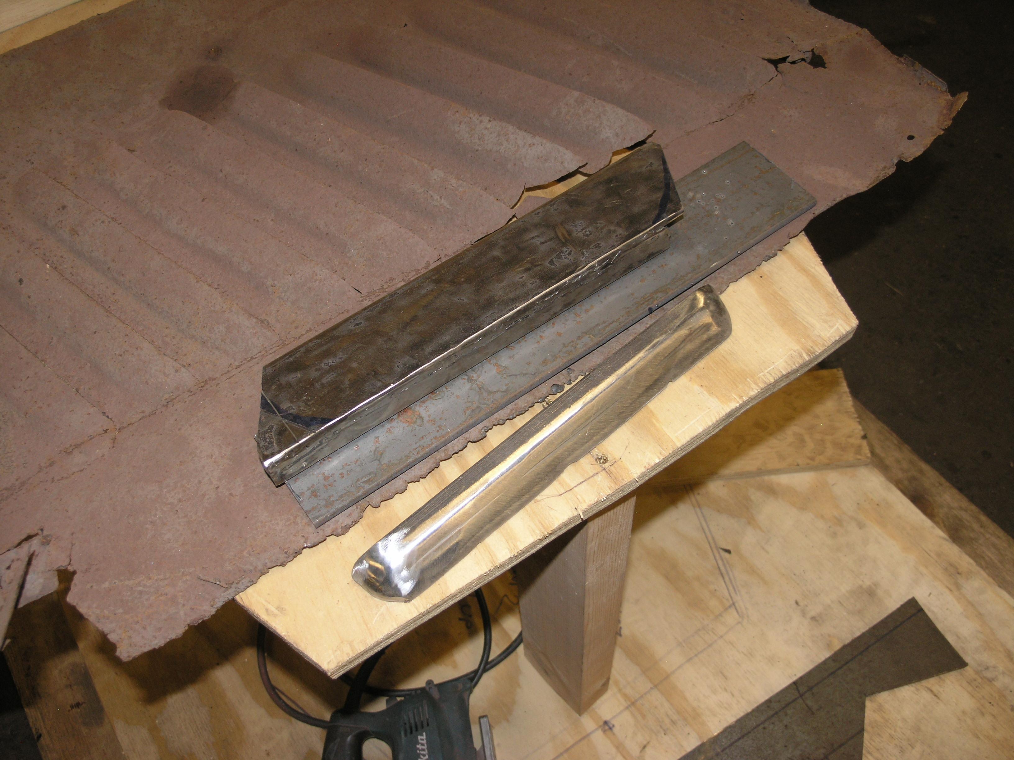
His latest bit of work for me, machining the AC flywheel to take a starter ring gear, can be seen here. Before doing it he had to adapt both the chuck and the gap block. -
1939 Mack FN Dump Truck
paulbrook replied to j hancock's topic in Antique and Classic Mack Trucks General Discussion
Astonishingly ten FNs made it to UK as part of a pre-lend lease deal. Sadly now all cut up (although I used to own a survivor). Its frame number is still etched on my memory - FN1C1181 -
1929 Mack Firetruck
paulbrook replied to SNelson's topic in Antique and Classic Mack Trucks General Discussion
The more I see it the more tempted I am.... Whereabouts is it? -
Interesting. Is that a Diamond T cab on the back?
-
1929 AC 5t Dump Restoration
paulbrook replied to paulbrook's topic in Antique and Classic Mack Trucks General Discussion
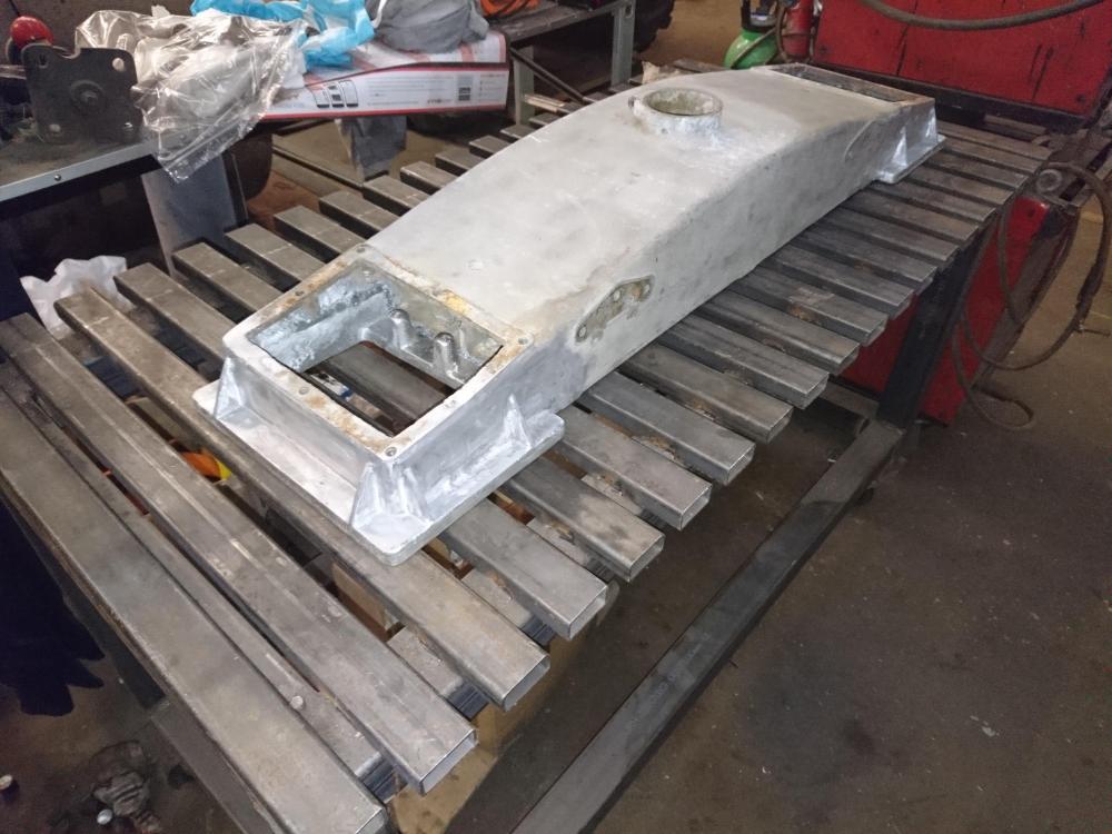
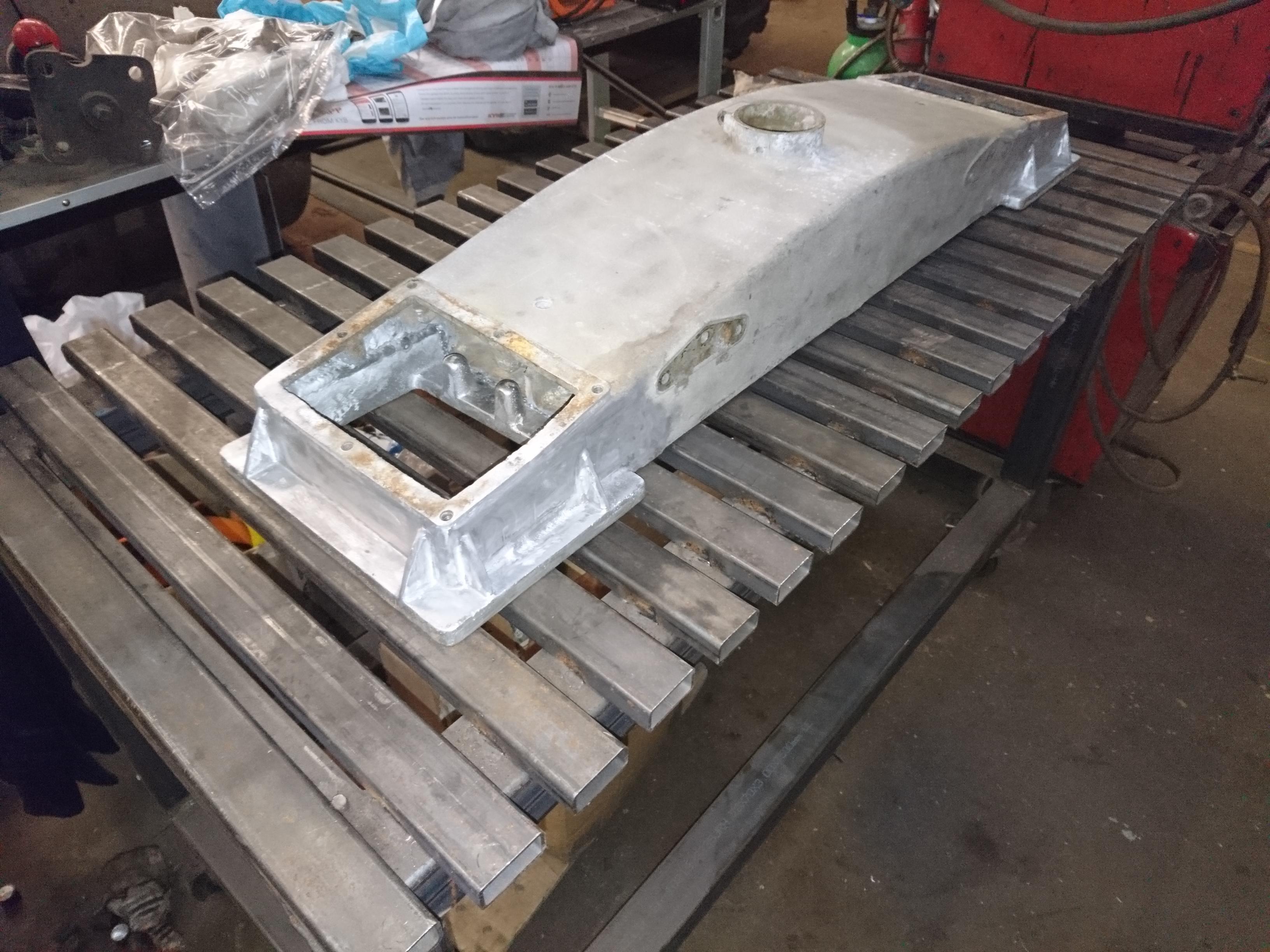
One thing's for sure - Dan's welds don't leak! He is a structural design engineer in the nuclear industry and really knows his stuff but also has a small company that do "impossible" engineering. So I think that the tank will be good for a hundred years or so. He did talk me through casting a new tank, and there is plenty that can go wrong with that too! Here is another of his masterpieces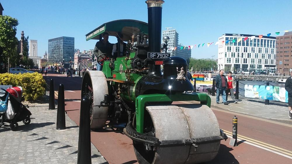
-
1929 AC 5t Dump Restoration
paulbrook replied to paulbrook's topic in Antique and Classic Mack Trucks General Discussion
Now that is a thing of beauty.. -
1929 Mack Firetruck
paulbrook replied to SNelson's topic in Antique and Classic Mack Trucks General Discussion
Wow that looks excellent and never mind what anyone else says well worth restoring! If you can get it to a seaport and into a container I could give it a home!! -
1929 AC 5t Dump Restoration
paulbrook replied to paulbrook's topic in Antique and Classic Mack Trucks General Discussion
All up I would guess about $3-400 for all this (like I say, I have not seen the bill yet!) but that involved all the set-up work. Now he has the files digitally I guess that subsequent repair sections would be much cheaper. We have done some work on another project (a WW2 Armored car) that is very rare. There is a similar one being restored by a group over on your side of the pond and we have been able to share all sorts of digital files which they can take to their local laser cutters, machine shop or foundry. I say take - they can email the files with the click of a mouse and the finished parts simply arrive in the post. That's what happens when you get some of these clever young folks involved -
1929 AC 5t Dump Restoration
paulbrook replied to paulbrook's topic in Antique and Classic Mack Trucks General Discussion
We were going to try that, but actually what we have now is the original but (virtually invisibly) repaired. On these old trucks much is so simple to make, like the cab, but over the years I have tended to want to try and use an original replacement or repair the original part if I can, even if that is harder than just, say, cutting a new cab side out of a sheet of metal. That said, sometimes only new will do! -
1929 AC 5t Dump Restoration
paulbrook replied to paulbrook's topic in Antique and Classic Mack Trucks General Discussion
I did not know you had a Packard. I have been dallying around buying a WW1 5t Packard from a guy I know in France for a few years now - but never plucked up the courage (besides I have too many projects as it is!). The 3d stuff that Dan is specialising in is a kind of half-way house: rather than try and print the final part he is printing the pattern from which a part can be cast, which makes it really cost effective. Many foundries can now print patterns, so if we want something casting out of some exotiv material we can simply email the file for the pattern to the foundry and they can then do a one off at little more than the cost of actually casting the thing. -
1929 AC 5t Dump Restoration
paulbrook replied to paulbrook's topic in Antique and Classic Mack Trucks General Discussion
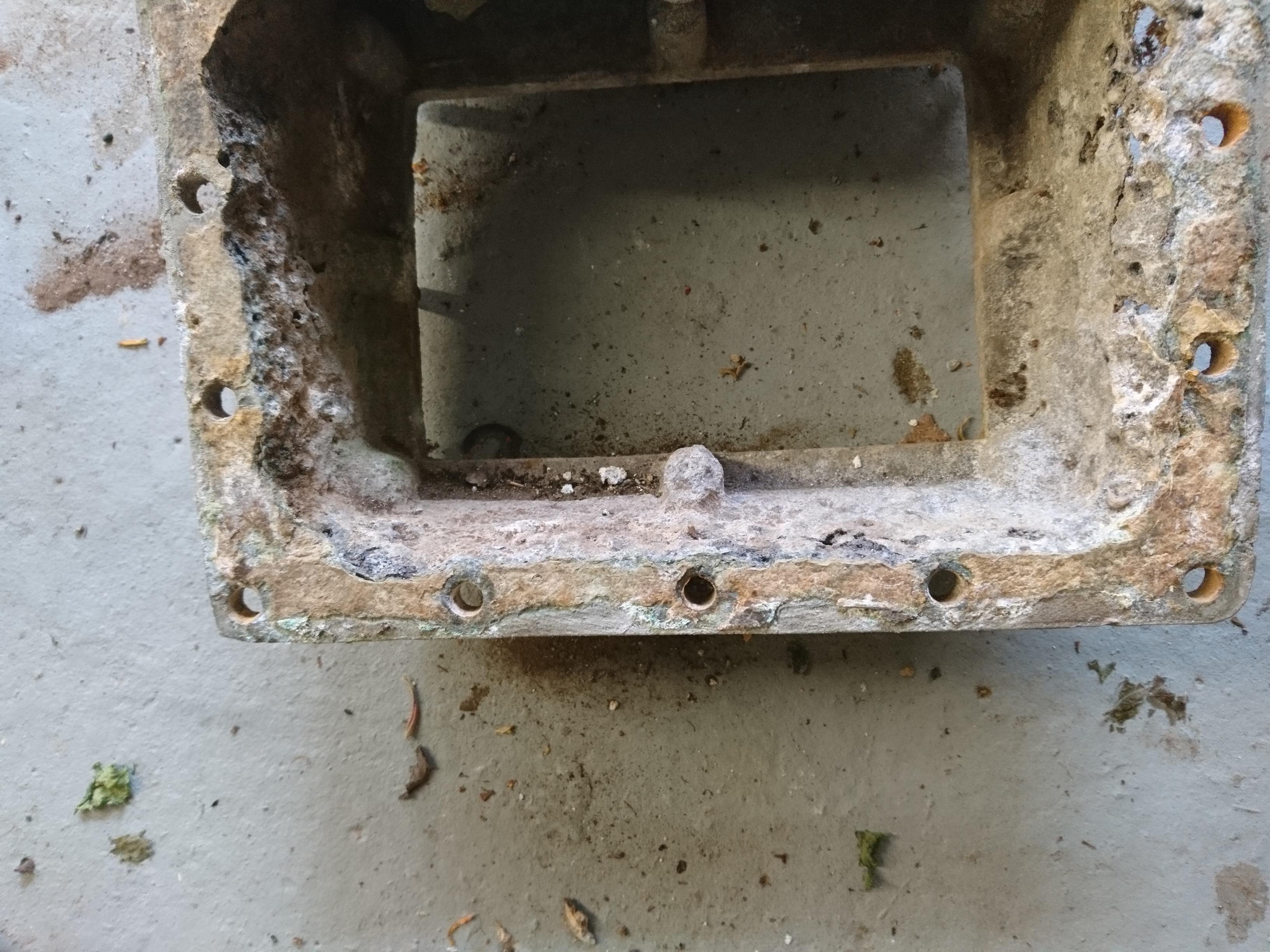
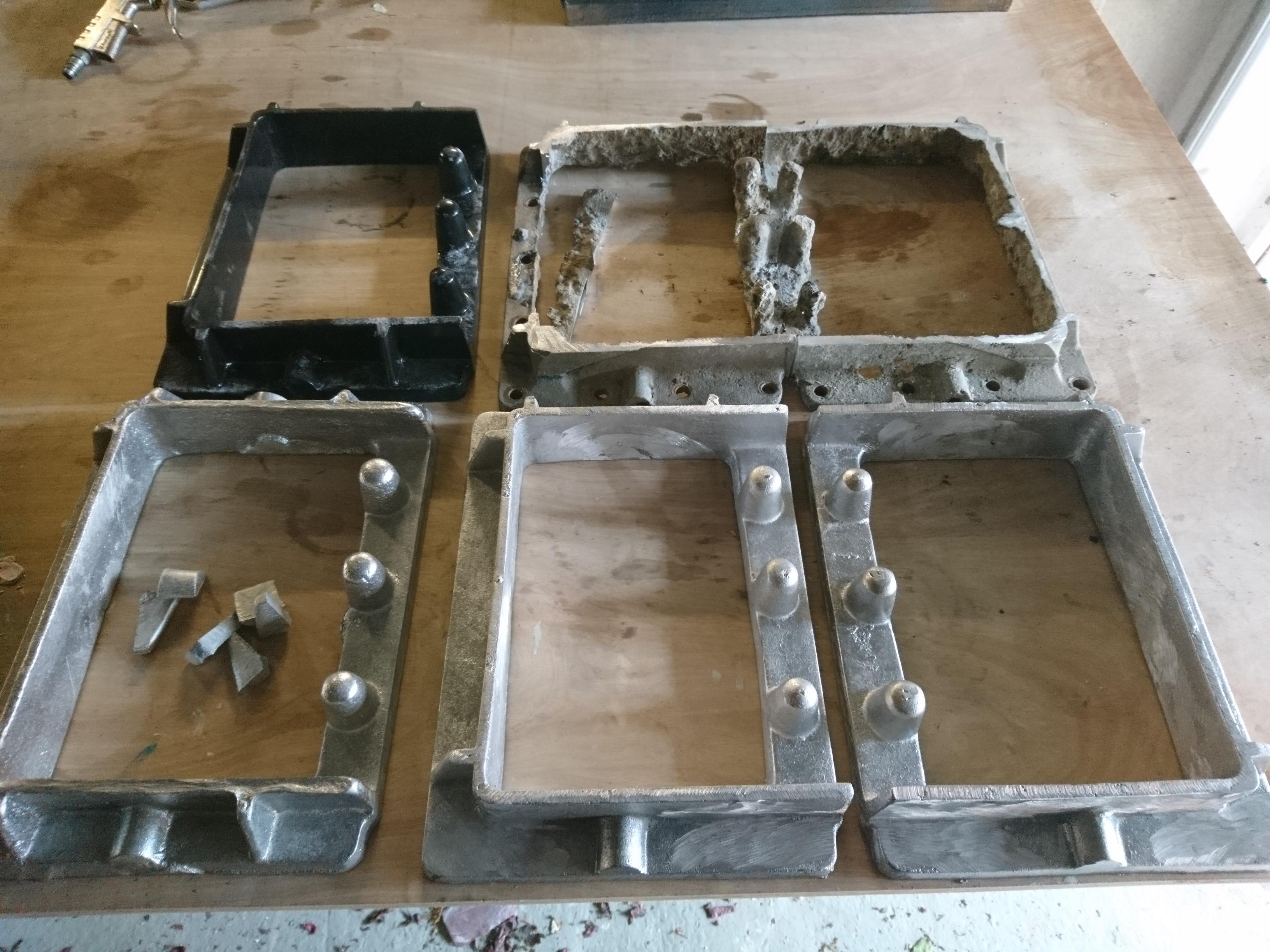
Dan has not sent me the bill yet! But the way he went about making the patterns was fascinating. First, he chopped out the rotten buts then set them up on a rotating table before scanning them with a laser scanner to form a 3d digital image. He then "cleaned up" the image to create a digital 3d image of what the repair part should look like. He then scaled it to account for the shrinkage when the part was cast before 3d printing the pattern using a foam that burns away as the molten metal is poured in. A simple sand mould casting was then pretty easy. He tells me that one of the advantages of the "lost" foam is that it tends to smooth out the casting surface - much more like die casting. I will ask him how long it took. -
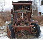
After quite a while since I first started with this project where other priorities got in the way, I have now picked up the pace on my AC restoration and thought that others might be interested if I posted a picture or two along the way. I have loads of pictures of progress so far hosted on a site called "photobucket": a link to the first album of pictures of my AC is here http://s484.photobucket.com/user/RustyTrucks/library/Mack as advertised but you should be able to navigate around my particular bit of Photobucket for lots and lots more. Just nearing completion is the restoration of the radiator which had suffered greatly from electrolytic corrosion of the aluminium top tank. after a little investigation my son Dan decided to get radical and designed, 3d printed the patterns and cast 2 new sections that he then welded into place to restore the strength and integrity of the tank. All the pictures can be seen here http://s484.photobucket.com/user/RustyTrucks/library/Mack AC Restoration 2019 but I have added a "before" "during" and "after" to this post just to give a flavour. Next job is to machine down the flywheel a bit, fit a starter ring and convert the engine to electric start - more to follow!


-
Properly timing a 1929 AC
paulbrook replied to ekennedy21's topic in Antique and Classic Mack Trucks General Discussion
It could be - if you are slightly to far advanced at idle it will run a bit quicker. More likely to be the carb though. As long as you don't get pinking when pulling with the ignition advanced then the spark must be more or less in the right place. -
Properly timing a 1929 AC
paulbrook replied to ekennedy21's topic in Antique and Classic Mack Trucks General Discussion
1. Check that the magneto points are set to the right gap (15 thou for a FU4) 2. Set the mag at full advance 3. Set cylinder no 1 (front of truck) to 20 degrees or 3 inches on the flywheel before top dead centre (check through the upper airduct hand hole, there is a pointer) 4. Unclamp the mag drive so that the mag shaft can be moved independent of the engine and rotate so that the distributor arm is pointing at the sector in the cap that corresponds to the lead running to No1 cylinder 5. Fine adjust the mag so that the points are just opening (you can put a bulb and battery across or use a multimeter) then clamp up the mag drive.


BMT Forum Logo
