
m16ty
-
Posts
351 -
Joined
-
Last visited
-
Days Won
2
Content Type
Profiles
Forums
Gallery
Events
Blogs
BMT Wiki
Collections
Store
Posts posted by m16ty
-
-
Drilled the frame today with a 1/2" hand drill. With the trans and mounts sitting in place, I took the mig welder and just put some small tacks on the mounts so they wouldn't move, and then removed the trans. After that I spotted the hole center with a 5/8 bit, drilled a 1/4" pilot, stepped up to a 7/16, and then finished the hole with a 5/8. I had good sharp bits so it actually went pretty easy.
Now it's time to mount the trans and get some driveline measurements for the driveline shop. Truck has 1880 joints, but the biggest yokes available for the trans are 1810, so both shafts are going to have to be made up with 1880 joints on one end and 1810 on the other.
Then I've got to figure out what to do about the shifter. The shifter Eaton offers for the trans is a rotary air switch, that would be mounted on the dash. I'm trying to find a push pull switch that I can mount on the main trans shifter. Only thing I've been able to find is a "2-way". In other words, down sends pressure out one line, all the way up sends pressure out another, and middle opens both ports to the atmosphere. If I use this valve, I will just have high and low with no neutral. I think this may work as I don't really see a need for neutral. Unless I'm missing something, the only thing I see neutral would be for is if you had a auxiliary mounted PTO. If I do add a PTO, I'll just put it on the main trans. Ideally, I'd like to find a 3 position push/pull valve that would send pressure to a 3rd port when in the center position, that way I could have a neutral.
-
9 hours ago, Freightrain said:
Mine has the horse shoe collar around the front, and just a piece of like 2 1/2" angle across the back. Both are sitting on rubber mounts. I don't think mounting it solid would do it any good. Any frame flex would try to break the mounts.
From the front looking back:
Here is what the back looks like, before I got it hung up there. It hangs from rubber mounts: ( I don't have crane access where truck sat, so I had to use straps to hoist it up)
Like I said, I need to check centerline heights, maybe I did drop the aux box some, but kept it at 4* down in the back to balance out the front u joints. Though since I did stretch the frame, I had plenty of room for the rear driveshaft and kept it at about the same basic angle it was before. Without some kind of frame stretch the box would not have fit with only 150" wheelbase.
Thanks for the pics. What you are calling the horseshoe collar is what the trans people call a trunnion mount. Mine has that also, and it has a grease fitting on the collar. I assume it is to allow for twist in the frame so the case doesn't try to twist.
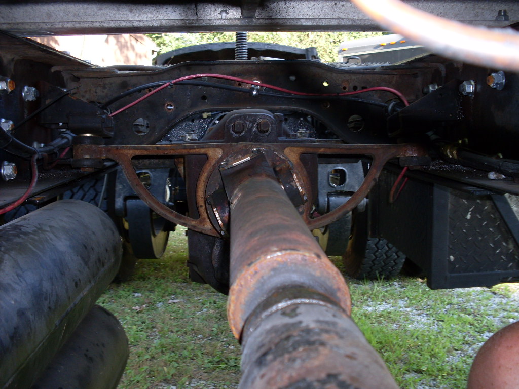
I redesigned my front mounts today to include rubber mounts. If I get a chance tomorrow, I'm going to try to drill the frame. I would love to use my mag-drill, but the fuel tanks are in the way. I think I can mark all my holes, take the auxiliary back out, and just hand drill it from the inside. I hate hand drilling frames but I think it will be easier than removing the tanks, and it will be easier to locate the holes by drilling from the inside. Right now I have everything just sitting in place, held up by shims on the frame flange.
-
14 hours ago, Freightrain said:
I forget where I found the information for when I put mine in. Seems they wanted the driveline angles on the center driveshaft to be equal to cancel out. My motor was like 4* down, so I did the same with aux. Since I stretched the truck 5ft, it didn't hurt the rear driveshaft so much. I'd have to go measure, I think I kept the basic centerline the same height in the frame. It runs smooth, so I guessed correct.
I know on lifted trucks, they rotate the rear axle upward to help eliminate u joint angle. I wonder if you could do the same?
It's my understanding that what you want to make sure of is that both transmissions are on the same angle. The way it was told me, is that any u-joint at a angle changes velocity each revolution, and that velocity increases the steeper the angle gets. What you want is for both u-joints to operate at the same angle, that is the front u-joint will change velocity a certain amount, and the rear u-joint will cancel it out, not passing the velocity change on down the line. The other thing you have to be careful about, even if both u-joints are operating at the same angle, is too much driveshaft angle, as there will be too much velocity change and cause a vibration in the driveshaft itself.
Spicer recommends trying to keep your driveshaft angle less than 3 deg if possible , but does ok having steeper angles. They just say u-joint life will suffer some at angles above 3 deg. Right now I'm sitting at 6 deg driveshaft angle, which I think is acceptable, as you see steeper angles than that in some factory setups. Spicer also warns against putting your driveshaft at zero angle, stating that if the u-joint never flexes it will just wear in one spot and the needle bearings won't rotate around the cup. Without precision measuring instruments, I doubt you'd ever get it that close anyway.
My only immediate issue I have now is rubber mounts. I've got the rear sitting on rubber mounts (borrowed off a military deuce engine mount) but am just planning on bolting the front trunnion mount solid. I hope I'm not making a mistake solid mounting the front mount. I'm kind of pressed for room on the front mount and the trunnion already allows the trans to rotate freely within the mount.
-
2 hours ago, ranchhopper said:
Im looking for an auxiliary trans if anyone has one for sale need it for a project it has a spicer direct drive five speed in it now and 50 MPH is top end.
I’ve got a Spicer 1241c available.
-
To make everything look better, common sense would tell you to raise the front of he auxiliary, to decrease the main to auxiliary angle, but the Spicer driveshaft publication says otherwise. The publication states that the main and auxiliary shafts should be no more than 1/2 deg within parallel to each other.
-
1 hour ago, Ol2Stroker said:
with the aux that low what would the rear driveshaft angle be?
Rear driveshaft angle is almost straight.
As it is sitting right now, the rear output of the auxiliary is roughly the same height and location of the original carrier bearing.
I think my current plan is to go ahead and mount it where it is, and I can always shim under the mounts to raise it if needed. Sitting level on the shop floor, the front rear has the capability to go up 5 1/2” before it hits the stops. If I raise the auxiliary much more than it is now, there is concern that the driveshaft could contact a crossmember, with the front axle in full articulation.
-
I don’t know if this should be in this forum or the driveline forum.
I’m trying to mount a Fuller at1202 in my RD822SX. I’m planning on having rubber mounts on the back mounts, and mounting the front trunnion mount solid.
There is just very little info to be found about how to mount a auxiliary. I did find a Spicer driveline publication that gave a little info. Where I sit now, both the main trans and auxiliary trans are sitting at 3deg tilt. To miss the crossmembers, the auxiliary is sitting quite a bit lower than the main trans, which makes my front driveshaft at a 6 deg angle. Spicer says that it’s best to keep driveshaft angle under 3 deg, but more is doable.
I’m just trying to set this thing up where it runs smooth and make sure I have it mounted right. Does anybody have any experience with mounting an auxiliary and can share any insight?
-
4 hours ago, jegster10 said:
I'm pretty sure Francis Engineering can fix or rebuild your manifold, might give them a call, heck they may even make new ones.
Thanks for the info. As of right now though, my $5 repair is holding strong.
-
 2
2
-
-
4 hours ago, Hobert62 said:
Now that's a shop!
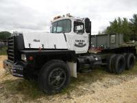
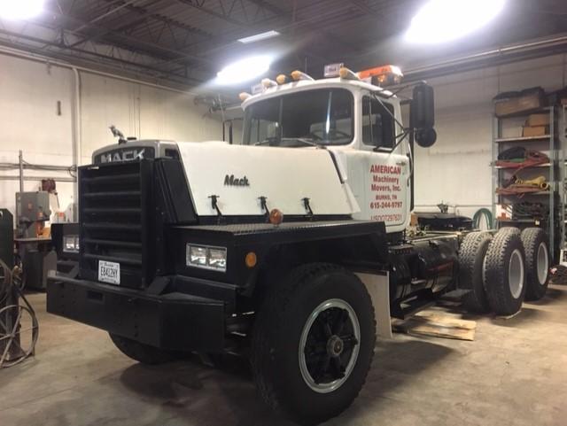
That is actually our warehouse the trailer is in, used to store customer’s machinery and goods.
The Mack picture is our shop, which is a sectioned off portion of the warehouse. The trailer would have filled up our whole shop, with no room to get anything else in there, which is why it’s in the warehouse portion.
-
7 hours ago, gxbxc said:
Can't you change the king pin on that trailer I though I had read someplace that they were interchangable .
Some military trailers have a interchangeable kingpin, but not that particular trailer. I’m sure it would be possible to permanently change the kingpin, but it’s a press fit and the kingpin shaft is also tied into the trailer steering mechanism.
I’ve got a 3 1/2” 5th wheel on the way for the Mack.
-
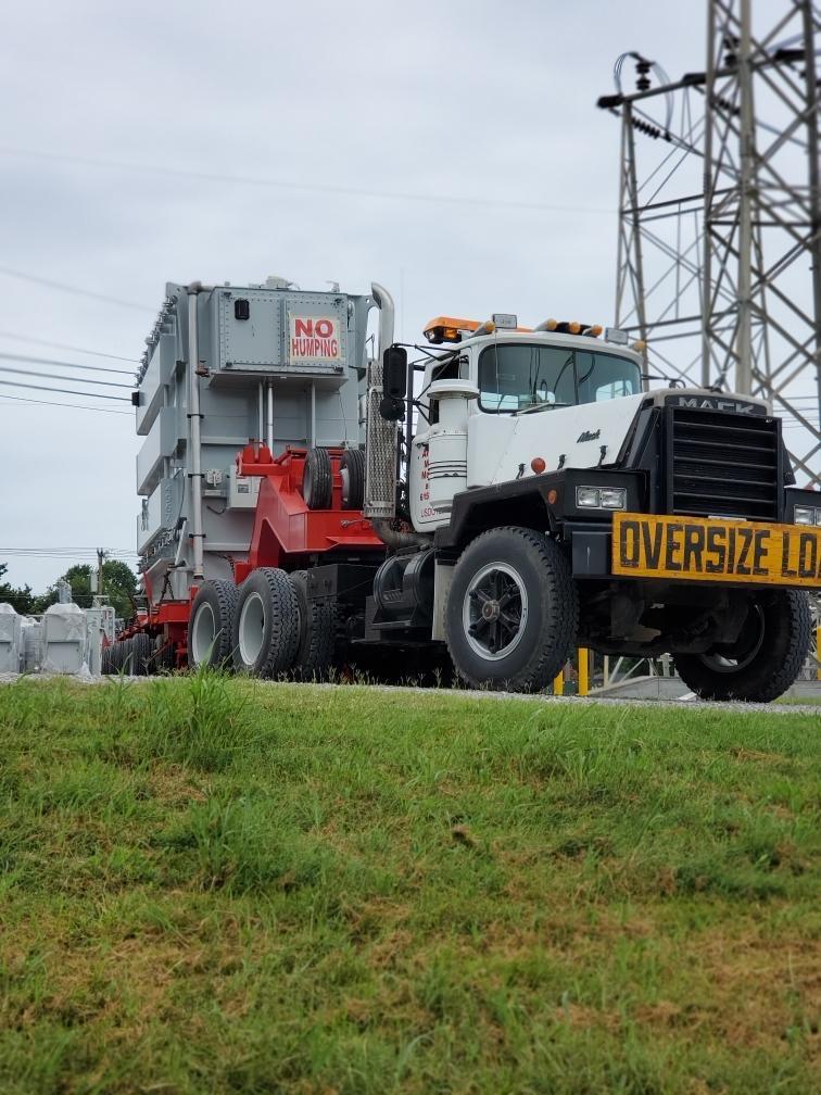
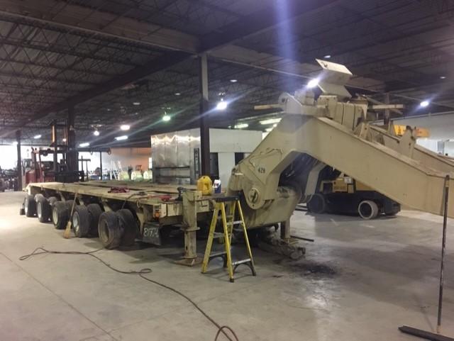
Got the trailer home. Ran the apu and what hyd I could (some broken hoses). Needs a little tlc, a few hyd lines, some air lines, and a few tires, but I'm working on it.
Also have the RD822sx in the shop awaiting a big 5th wheel and a AT1202 auxiliary.
-
2
-
-
On 11/9/2018 at 7:39 AM, Outbehindthebarn said:
I can't find the 1/8 inch rope.. do you have a link?
Here you go- https://www.mscdirect.com/browse/tn/?searchterm=rope+gasket&hdrsrh=true
-
I’ll try to get a pic today, but all you can really see now is the hose clamp. The rope is almost too flexible, requiring 2 sets of hands to work it into place.
First thing I did was clean the joint the best I could, getting down into the crack as much as I could. The 1/8 rope is small enough to be worked into the crack. I just kept working it around the pipe until the crack was full. The 1/4 rope went on the outside, but still on the taper of the female piece, using the hose clamp to push the rope against the taper and force everything tight to the joint.
I also found that there are two different types of high temp rope gasket, silica and fiberglass. The silica has a rating of around 2,000 deg and the fiberglass had a rating of around 1,000 deg. I went with the silica, although it is twice as exspensive, but no more than I used, I think I had around $20 in material.
-
- Popular Post
- Popular Post
Well today I decided to tackle the manifold leak. I ordered some silica rope gasket from MSC in 1/8" and 1/4" diameter. Took the 1/8 and was able to force it into joint with a screwdriver for 3 rounds. Next I rapped the 1/4 around it 3 rounds and then forced it in tight with a hose clamp.
After a test run, everything is holding good. The silica rope gasket is rated for around 2,000 deg.
-
4
-
I had some dumptrucks in the mid-1990s. We were getting $50 per hr back then, and it wasn’t enough.
-
I guess I have to ask why?
-
22 hours ago, AZB755V8 said:
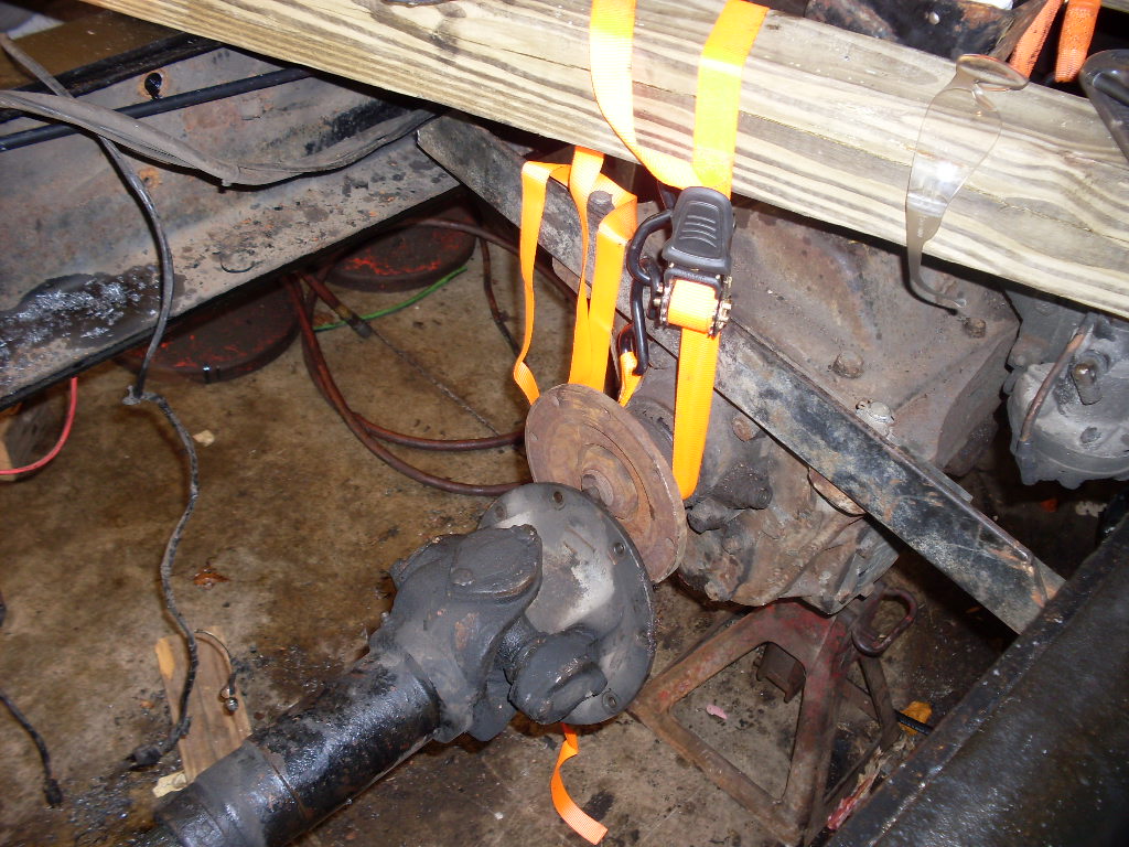
I don't think that a 1710 yoke will work with a 1810 yoke in the first place. The across cap dimension are 6.094 and 7.547 respectfully. An 1880 is 8.094 across. Get the 1880 on one end and a 1710 on the other end of each driveshaft would work. Doing so would just have a much lower torque rating for the 1710 u-joints. Maybe the Aux Trans has a lower torque capacity as well.
I guess I wasn't clear in my first post. The auxiliary came with 1710 yokes, 1810 yokes are available for the auxiliary. The torque rating for the AT1202 is 35,700 lb-ft, the highest rated auxiliary I could find.
Looks like I'll have to do what Freightrain mentioned, have the driveshafts made up with the original 1880 yokes on one end, and 1810 yokes on the other. I've got a couple of more phone calls to make to people that work with these transmissions a lot, before I cut anything up.
Are 1880 joints that uncommon on large trucks? It's the first ones I've seen, but it's also the first RD800 I've dealt with. They list the Fuller AT1202 as a factory option on the RD800 series, so you'd think somebody would make yokes to fit it. It just seems kind of counter-intuitive to add a auxiliary trans to increase torque, and then weaken the driveline.
-
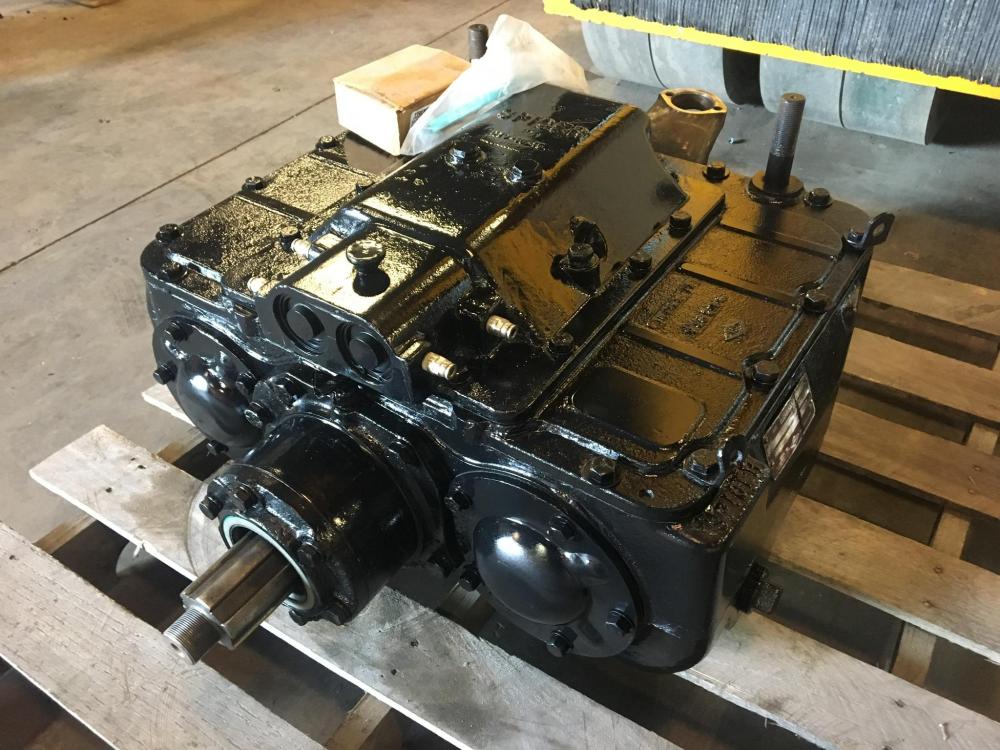
I’ve picked up a Fuller AT 1202 auxiliary trans for my RD822sx. The trans came with 1710 yokes, but the Mack has 1880 driveline. I can’t find a 1880 yoke anywhere to fit the Fuller AT-1202. My local driveshaft shop says the only thing he knows to do is make up 2 driveshafts with 1880 joints on one end ( to fit the main trans and rear end) and 1810 joints on the other end of the driveshaft to fit the auxiliary.
Anybody got any other ideas?
-
That is a good deal. If I needed one, I'd be all over that. Shoot, if I were closer, I'd almost buy it for a spare.
-
18 hours ago, Outbehindthebarn said:
I have a suggestion... try ramming some aluminum wire into the groove, tapping it in and around using a flat head screw driver. Could use copper too, but I think aluminum expands more than copper. Worth trying. In my experience, putty probably won't work.
I like this idea, I may give it a try. I’ve seen asbestos type rope that I’ve also thought about, but I’ve never seen any of it in a small enough dia to fit in the gap. The thinking was, get it shoved in there as far as you can, and then put a hose clamp against the joint to keep it from backing or blowing out.
I’m also contemplating welding. It’s a joint that wouldn’t have to come apart in the future. The only problem is, it’s in a bad spot and I’m not sure I can get in there to weld it all the way. I’d rather try that first though, than some sort of sealer. If you use the sealer first and try to weld later, then you have the problem of removing all the sealer.
-
1 hour ago, fjh said:
highly doubt the the vac thing as you have open valves to fight with the chances of getting a total vacuum is slim to impossible at best !
If your valves are working right, there should never be an air passageway from the exhaust manifold to the atmosphere (other than out the stack). There may be a intake or exhaust valve open, but never at the same time.
-
I’ve fought for 2 afternoons trying a minimally evasive way to remove the leaking joint, now I’m ready to give up. Only way I see at this point is to remove the whole passenger side manifold to get it apart.
I think I’m going to try some exhaust putty and see if it works. I’m just afraid I’m going to end up with broken bolts and all the joints leaking, if I try to take it all off. Has anybody used the putty with decent results? I saw a YouTube video where a guy put a shop vac into the exhaust outlet when he applied the putty. Claimed it would suck the putty into the leak, makes sense to me.
-
14 hours ago, kscarbel2 said:
Of course Henry Ford was very close friends with Hitler as well. Hitler kept a photograph of Henry Ford on his office desk. Ford received Hitler's "Grand Cross of the German Eagle" in 1938.
Ford is the only American mentioned favorably in Mein Kampf, although he is only mentioned twice:[62] Adolf Hitler wrote, "only a single great man, Ford, [who], to [the Jews'] fury, still maintains full independence...[from] the controlling masters of the producers in a nation of one hundred and twenty millions." Speaking in 1931 to a Detroit News reporter, Hitler said he regarded Ford as his "inspiration", explaining his reason for keeping Ford's life-size portrait next to his desk.
https://en.wikipedia.org/wiki/Henry_Ford
.
Ford must have changed his tune, or at least didn't mind reaping profits of Hitler's defeat. Ford was heavily involved in the war effort, being the major supplier of Jeeps, among other things.
-
For sale is a Spicer P1241c auxiliary transmission. 4 speed, LL, L, Direct, OD.
Had a bearing down in it. We tore it down, inspected, replaced bearings and input shaft, and rebuilt air-shift mechanism.
Asking $4,000.
Would consider trade for Fuller AT1202.
-
1
-

BMT Forum Logo

Fuel for a B model
in Antique and Classic Mack Trucks General Discussion
Posted
I've heard of people adding 2-stroke oil. I haven't done it myself but I doubt it would hurt anything.