

Vladislav
-
Posts
8,138 -
Joined
-
Last visited
-
Days Won
79
Content Type
Profiles
Forums
Gallery
Events
Blogs
BMT Wiki
Collections
Store
Posts posted by Vladislav
-
-
Happy Happy Birthday guys!
-
There are two basic kinds of solder. 40% tin with 60% lead and opposit - 60% tin with 40% lead. The 1st is generally used for electronics. It melts about... hmm, sorry guys, about 200C. That's that solder you find with flux put inside. The other kind has higher melt temp and higher mechanical strength. Here it usually sells as thick sticks. It's more for mechanical jobs and can be used with solder acid for work with steel and SS. But for some reason I haven't had much luck using it (not enough skills?)
-
 1
1
-
-
Happy Birthday!
We haven't seen you for a while on here.
-
21 hours ago, hicrop10 said:
I have mentioned this before and got some great response.But I’m still lost.First question will be how do I know if my truck is positive or negative ground?Secord question what the hell m I doing wrong.I have provided some diagrams of how I have my truck wired up.When the truck is running or not the whole thing is hot.By that I mean touching my test light against anything it lights up(steering column,frame,oil filter and so forth).Any help would be greatly appreciated.When it is running it runs great.I have a rebuilt generator for it and a new voltage regulator,I don’t want to damage them.


Do you have any wire connected to the chassis rail as a ground? I mean one which is straight connected to any battery terminal. Or is one of the starter connections gets to its housing so further connected to the flywheel housing, engine block and the chassis?
-
As I remember I also initially contacted Barry via PM on the site.
You can always find his posts in the Site Related Topics.
-
2
-
-
Congrats on the rare catch up Paul!
Well done!
-
A pump needed to fill up the torque converter. Normally the front one does that driven by the crankshaft of the engine. I'm familiar with Mercedes auto trannies only and there's (was) additional pump put in the rear of the unit driven by the output shaft. So when you make a rope start getting the car rolling about 25-30km/h you need 30-50 meters for the oil to fill the converter so spinning of the wheels gets transmitted to the crankshaft.
As long as engine gets fired up and the front (main) pump develops pressure that pressure pushes a plunger shifting off the additional pump drive deactivating it.
That was a handy setup Mercedes kept in production unitil 1990-1991. Than they eliminated the pump putting just a cover in its place. I once had a funny situation when I test drove a freshly rebuilt tranny. After driving fine for 2-3 km I got to a wide paved spot to make a U-turn. Had to stop to pass traffic and when pressed gas pedal found no car movement. Figured my shop guy mismatched front pump drive coupling when was installing the tranny and ruined it. We had that done multiple times with those cars (W126 S-class of 80's-early 90's). Usually a car doesn't move initially after transmission installation but there were 2-3 times when it drove for some while and quit later. That was one of those cases. The spot I used for the U-turn was at a top of a hill and my way back to the shop was downhill. So I bit the bullet managed wide enough interruption in the traffic (needed to cross he opposite lane), pushed the car by hands a bit to get it slightly rolling downhill and in a hundered or so meters switched to D. I was rolling about 25 km/h at the moment and the engine was running. Pressed gas and felt good reaction. Drove 3 km back successfully and luckily needing no stops. The first one turned out in front of the shop gates already and there we had to push in by hands. Transmission removed front pump swapped.
-
2
-
-
Welcome to the groupe!
The truck looks great!
I wish you good luck to get it ready hitting the road soon!Vlad
-
1
-
-
- Popular Post
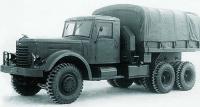
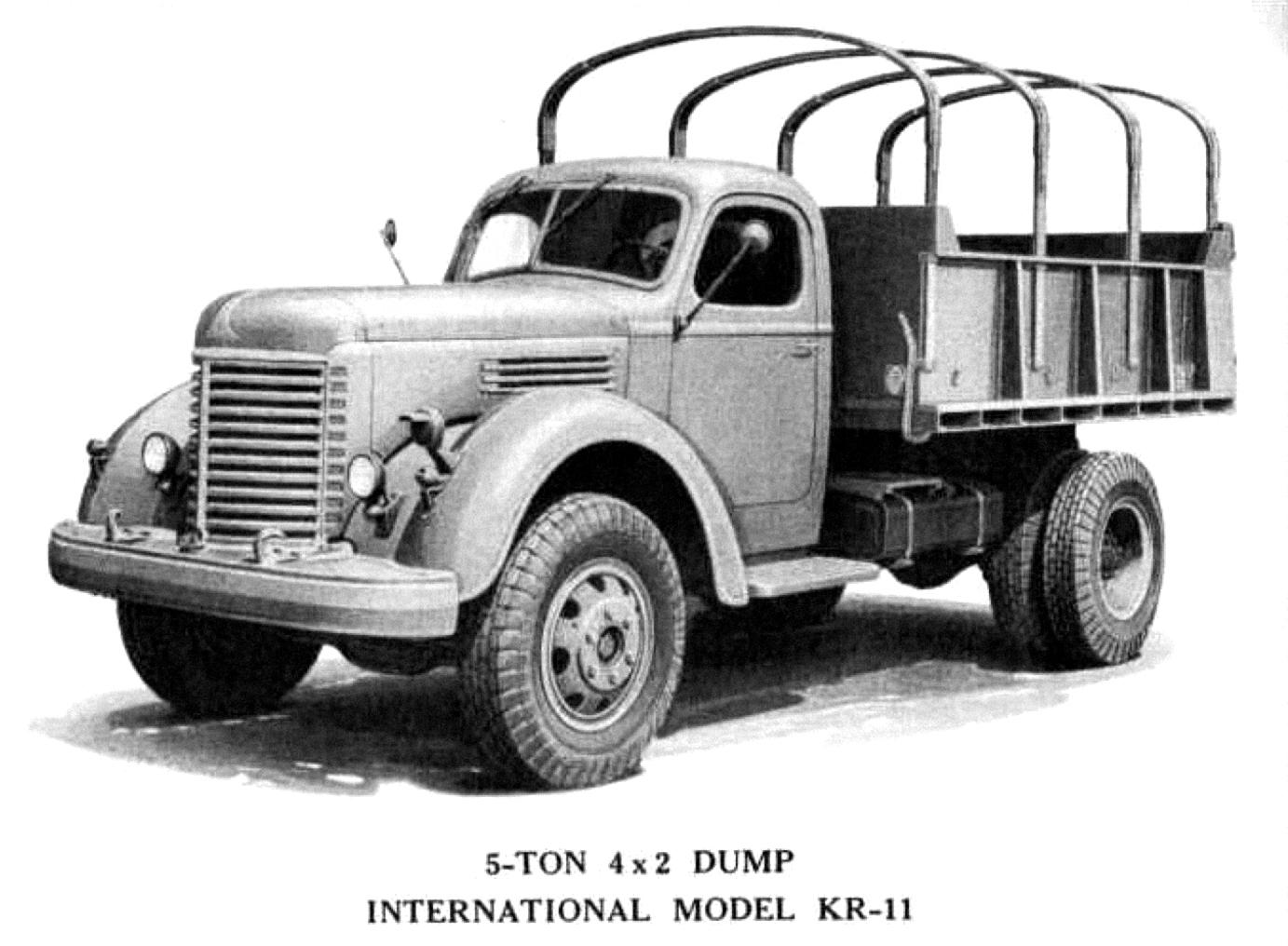
During WW2 under Lend-Lease some handful of IH KR-11 dump trucks were supplied to Soviet Union. None of those known survived and even not many photos of them in service here too. Would be cool to find a similar one and import. But that's out of my capabilities at the moment.

-
4
-
 1
1
-
- Popular Post
Two wooden barrels put at the front of the bed right behind the cab would add country look. And could be used as luggage compartments perfectly.
-
2
-
 1
1
-
- Popular Post
Joey, step by step makes long ways covered. I remember you mentioned this project multiple times in other threads and it's a good idea to compile everything at one place. I'm going to keep my eye for updates. The truck looks like in a very good solid shape which means excellent potencial. And once the mechanics/electrics are ready you might put efforts to the paint or maybe just clear coat or even maybe some other unusual artificial solution. I picture the truck with flat bed body maybe with stakes or with a long narrow tank or maybe some special type of structure which would bring look and help using it to drive to a grocery shop sometimes. Good approach to the electrics. Modern stuff should not be seen on a classic rig but it can make its job done.
-
1
-
1
-
 1
1
-
On 5/6/2026 at 2:28 PM, other dog said:
We heard a noise around 1:30 this morning so I got up and looked around. Looked like the wind had blown the trash can over on the back porch.

An old picture I ran across from when I had the Dodge pickup.

Is that the wind with the tail and two ears or just an old photo?
The beer distributor has impressive look no argue but my highest bid would be for the Sand and Gravel.
Hope Zina enjoys the pickup and can handle manual steering. As we know desire means more than capabilities.
-
2
-
-
- Popular Post
Nice! I like the look of these IH's.
Maybe you know Russia produced ZiS-150 trucks after the war with design grabbed from the IH. But slightly reworked with wider cab and flat head engine.
Just wonder how can you find the time t work on this project?
-
2
-
1
-
- Popular Post
- Popular Post
Happy B-lated B-day Brocky!
-
3
-
1
-
Hi and welcome to the group!
Answering your question. I honestly don't have the particular point. The most vehicles I have ever dealt with (probably same to you) the oil gets up to the filling hole. But service manual for my 1945 Mack truck (tandem bogie though) prescribes to fill up to a level of one inch lower than the filling hole. There's a nuance that truck has wheel bearings separated from the banjo and they're greased don't get any oil from the differential. Your bearings get oil from the banjo I guess so I'd keep the level up to the edge of the hole. There could be an option to check if you remove one wheel hub and see the level in the banjo the oil starts leaking from the jack shaft tube to where the bearings are expected to be. That would be a required minimum to my understanding but seems easier to just fill up to the plug.
Hope this may help.
Vlad
-
1
-
-
On 5/4/2026 at 5:58 PM, james j neiweem said:
Did the H-65 look like the H-63? What was the difference/upgrade?
Do you like this?
Just go to the top of the page.
https://www.bigmacktrucks.com/collections/item/867-h65/?tab=comments#comment-194
-
1
-
-
And I doubt there are many (any?) chances to find a factory single axle R with air ride at the rear. B's are out of that point definitely. There were converstion made by owners though.
-
Just now, mowerman said:
Forgot to mention, they were all painted Allied van lines, colors, and all in really good shape like they had been restored
Bob, how did they look in Allied Van lines colors those days? Bright orange all over?
I like the look of them H's.
-
H-65 - a non-sleeper cab? Or am I wrong?
-
- Popular Post
- Popular Post
Well I see well enough that the grass is green and the dogs are pretty but hell where's that wagon with the rocks?? Ain't any unknown Winfall lady accured/adopted them for any reason?
-
2
-
1
-
Thanks for the service Barry.
I hope we will survive after one more software update
")
-
1
-
-
- Popular Post
- Popular Post
On 4/28/2026 at 2:20 AM, Freightrain said:Tired, broke man....
That's exactly that state that may be described as happiness. I'm sure you know it. Just can't confess until the truck is ready to go.
-
4
-
Happy B-day Joey!
Best wishes!!!
-
1
-
-
Yes, very clean job with clean welds. And as I noted multiple Mack trucks had tranny mounts made similar way from the factory. Hope you was able to count out desirable position of the engine well enough.


BMT Forum Logo

Pictures of the Week
in Odds and Ends
Posted
BTW which island is usually static? That long one or the closer one to you on the way to Brooklyn?
And that trick with limitation of use of lead in the plumbing makes sence but also limits strength of the soldered points. Cooper itself is poisonus so seems doubtful limiting lead presenting in tiny junctions only.