

Licensed to kill
-
Posts
582 -
Joined
-
Last visited
-
Days Won
9
Content Type
Profiles
Forums
Gallery
Events
Blogs
BMT Wiki
Collections
Store
Posts posted by Licensed to kill
-
-
-
The key with exhaust temps is RPM. There is a difference between pulling with an EXT of, say, 1100 degrees at 1200RPM and 1100 degrees at 2000 RPM. The more air you pump through the cylinders the less effect those high temps will have. This does not mean that keeping the RPM high negates any concern but, rather, if the RPM is LOW, any high exhaust temps will be much more likely to cause damage.
-
 1
1
-
-
18 minutes ago, mattb73lt said:
That may be an easier route then an entire frame swap regarding mounting the cab, and later, the legalities of registration later.
Different jurisdictions may be different but I don’t see registration as an issue. It will be registered as the plate on the door states. A case in point, years ago I bought a smashed up 2004 dodge single wheel 3500 Cummins (was jack-knifed with a goose neck trailer and smashed the cab/box). Bought a 2004 dodge 1500 with a good body but blown motor, put the body on the 3500 chassis and put it back on the road. Had to register it as a 1500 (as per the vin) and just changed the fuel to “ diesel”. There was no question about the chassis. However, like I said, this may vary by jurisdiction.
-
That is what I am trying to to but no luck. However you can find it at “Canadianrodder” forum, then search “ project gunsmoke”. Let me know if you find it.
-
1
-
-
Sorry, I just can remember how to attach the link (I HATE computers!!!!!!)
-
Since I have just recently travelled this path (and am still on it), I will just share some of the things I did and how I did them just for some ideas for you to say “hey, that’s a good idea” or “ well that is stupid, I won’t be going that route”. Bear in mind that my project is still under construction so some of the directions I have taken are yet to be road tested. At any rate, here is my built thread thus far and I welcome any thoughts or ideas you may have.
-
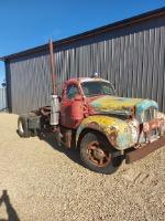
Couple things, first, the axle on the CH is likely 2” wider than the b61 axle and as such, will set the wheels too far out relative to the fenders. Of course, this is the same for the rear but the rear will not show the width difference like the front will and, I don’t know how you would mount the front axle to a narrower frame due to the way they are mounted. Regarding the rear, while cutting off the frame and grafting it to the b61 frame is a common route to take, I chose to mount the suspension to the b61 frame. Was not difficult to do and, IMO looks a lot better and less “cobbled” together.
-
Hard to tell in the pics but the little bit if frame showing in the 3rd pic of the B61 show that frame to possibly be in pretty good shape, maybe as good or better than the CH frame. IMO, a lot easier to retrofit the air ride suspension to the B61 frame than the B61 cab to the CH frame (with the added bonus of the serial number on the door and frame matching when you are done. However, I suspect that the CH frame has a power steering box (and you probably want that) BUT, how will that line up with the B61 column?????, don’t know but probably not. There is a LOT to consider when doing acab swap like that, steering, clutch, cab mounts etc. however, when it comes to the clutch, a frame swap MIGHT solve a few issues depending on what you go with for a trans. The B61 uses a “push” style clutch where most (all?) newer trucks run a “pull” clutch so the linkage works in opposite directions. When I was gearing up to do my b61 project, I went through many of the same ponderings that you are. I settled on an E350 ( because the deal seemed right) but I think the typical 237 swap is probably the best choice. Would love to follow your progress hope you keep the thread going. Thanks for sharing
-
1
-
-
- Popular Post
- Popular Post
Smart wife. Buy you a project to keep you out of the house and in the shop. That is how marriages last. 😁👍
-
3
-
 2
2
-
- Popular Post
- Popular Post
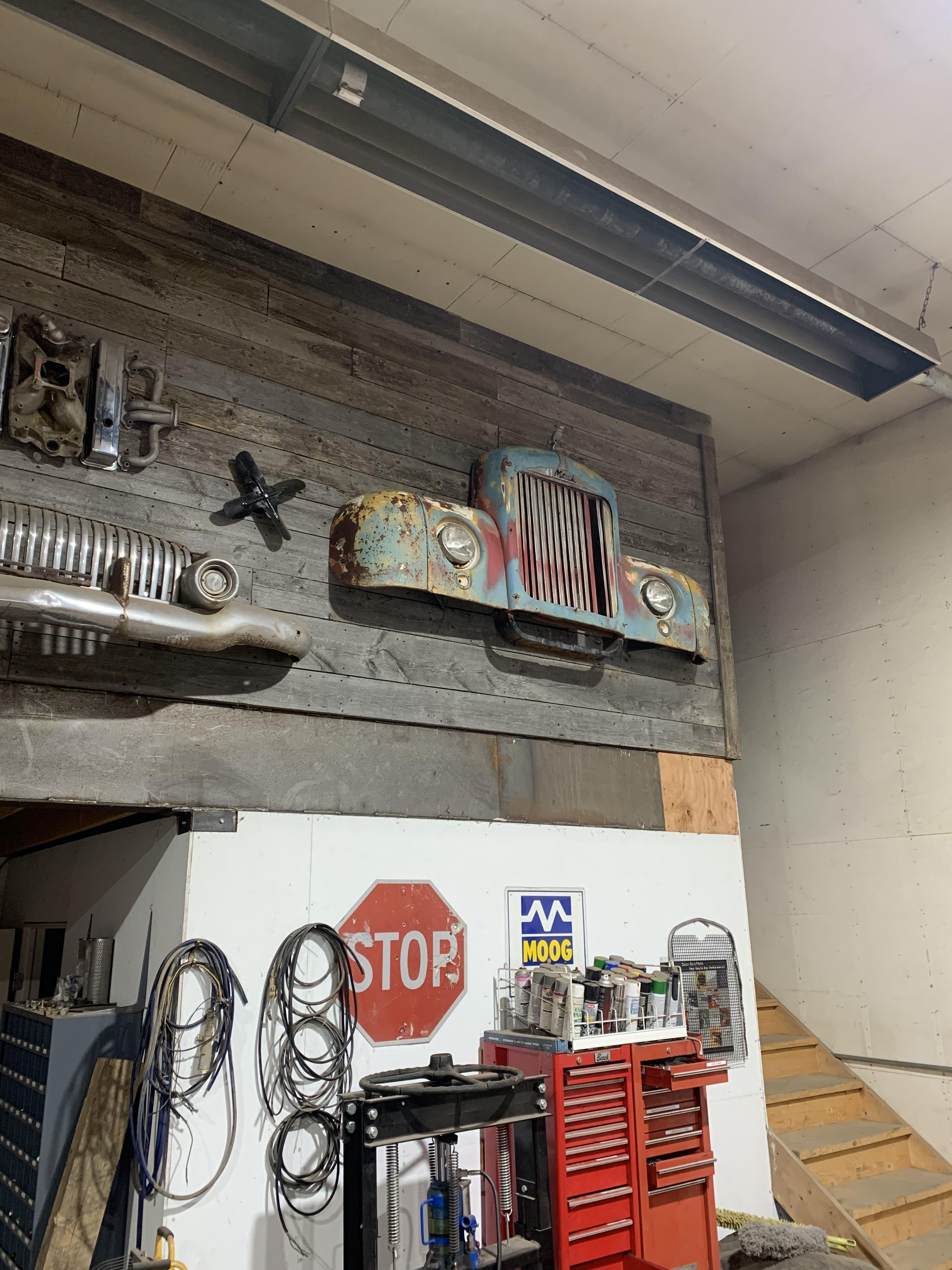
Great idea for old T’s. I don’t have any “Mack” themed T’s but do like to repurpose anything in the name of “art”. A couple Mack themed “art” here. Shop art.
 Yard art.
-
3
-
2
-
On 11/15/2024 at 7:03 AM, fjh said:
Post a picture!
-
1
-
-
52 minutes ago, fjh said:
Is your pump Ambac or Robert Bosch? This was used on both at one point however later on they changed to the lda style more universal to other manufacturers! Like Cummins and John deer!
No idea what pump is on this engine and do not know how to identify it.
-
6 hours ago, mrsmackpaul said:
Sorry, I thought I explained that
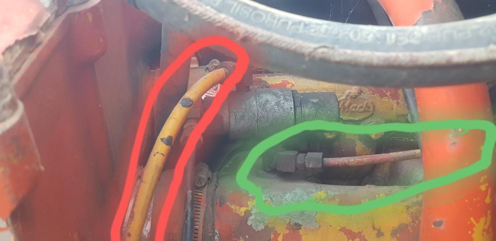
The one with the badly drawn red circle goes to the little air ram on the injector pump that limits travel until you get boost or are out of reverse and 1st gear
The green line goes to the fear box, reverse and 1st gear doohickie
The uncircled line is the air supply to the puff limiter doohickie
To be honest I only looked at these for a few minutes and relied on my memory
Paul
I went back and re-read your previous post and, yes, you did explain it there. Somehow, when I read that it went right over my head and I wasn’t following. Don’t know why as it seems pretty clear now. My engine had the supply line but both others were plugged. Of course I have no provisions for that on my trans but I also don’t see any place on the injection pump for an air line either. It is possible that the pump was changed for one without this provision and that could be why the port on the limiter is plugged. I dunno.
-
1
-
-
On 11/13/2024 at 2:40 AM, mrsmackpaul said:
But wait theres more
So were do these air lines go
Green circled airline goes to the gear box, reverse, first
Red circled airline goes to the injector pump rack
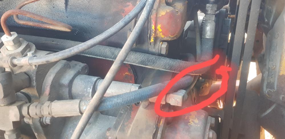
Now crusieliner 64 Paul
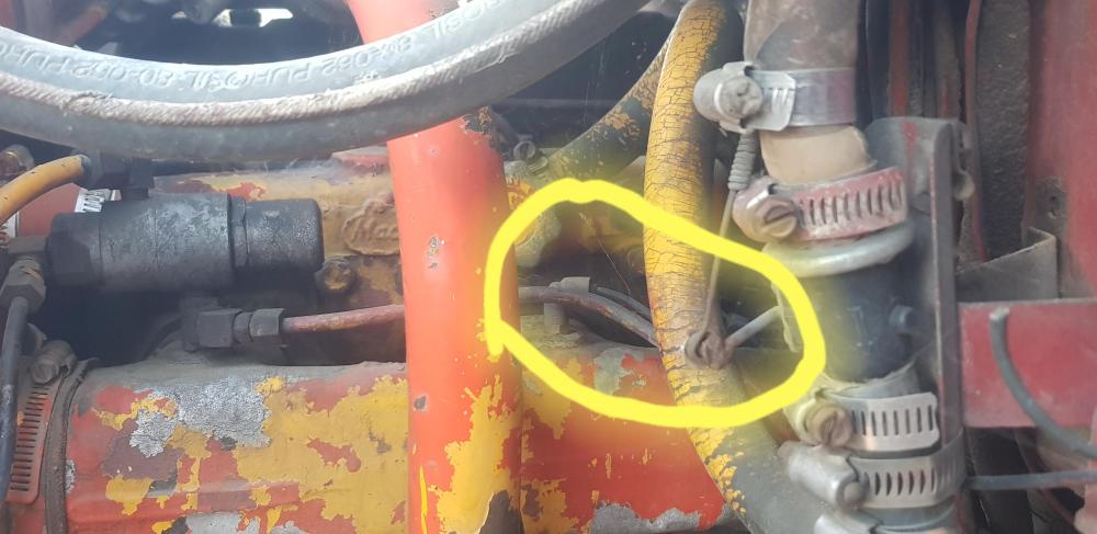
This looks like a simple piston type of deal, I can see bleed holes etc to let air out and or in
Yours should be a piece of piss to fix over a few pints of your favourite larger
Bellow is the air line to my boost gauge
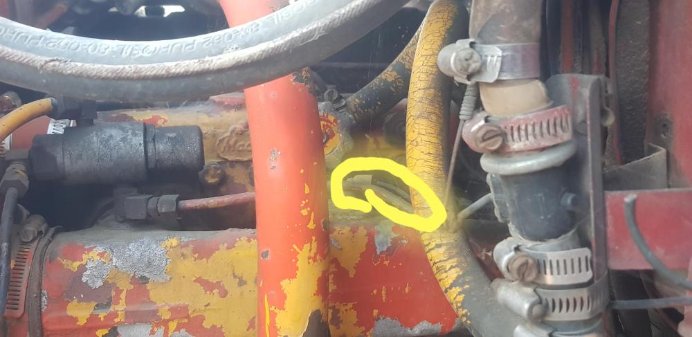
Hang on I'll zoom in on this
Dunno if any of this helps, bit old mate the sorted your motor has jiggered up the plumbing department
Licensed to thrill your missing a (as the younger set say out here) "a shit ton of boost"
I wonder if the breather is for a cab over type of deal, possibly a garbage truck
Dunno if this helps or not
But everything is a bonus
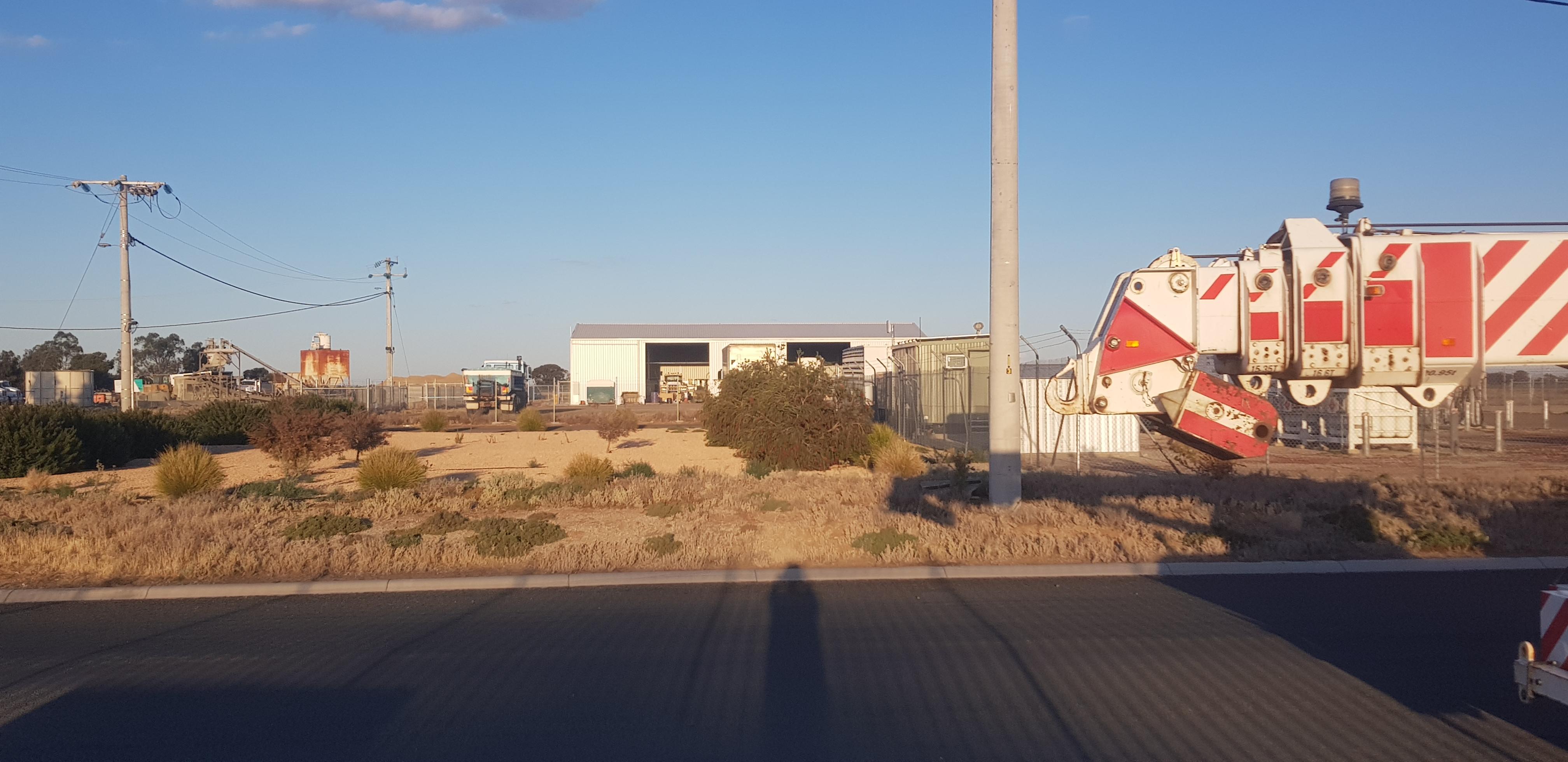
While sorting the pics I spied this a wee distance away

Yeah a boom of a crane, woopty bloody do Paul

Okay a bit more, fresh meat lol
Not a cool power, but still cool enough
Paul

Do you know where those air lines from the puff limiter go?
-
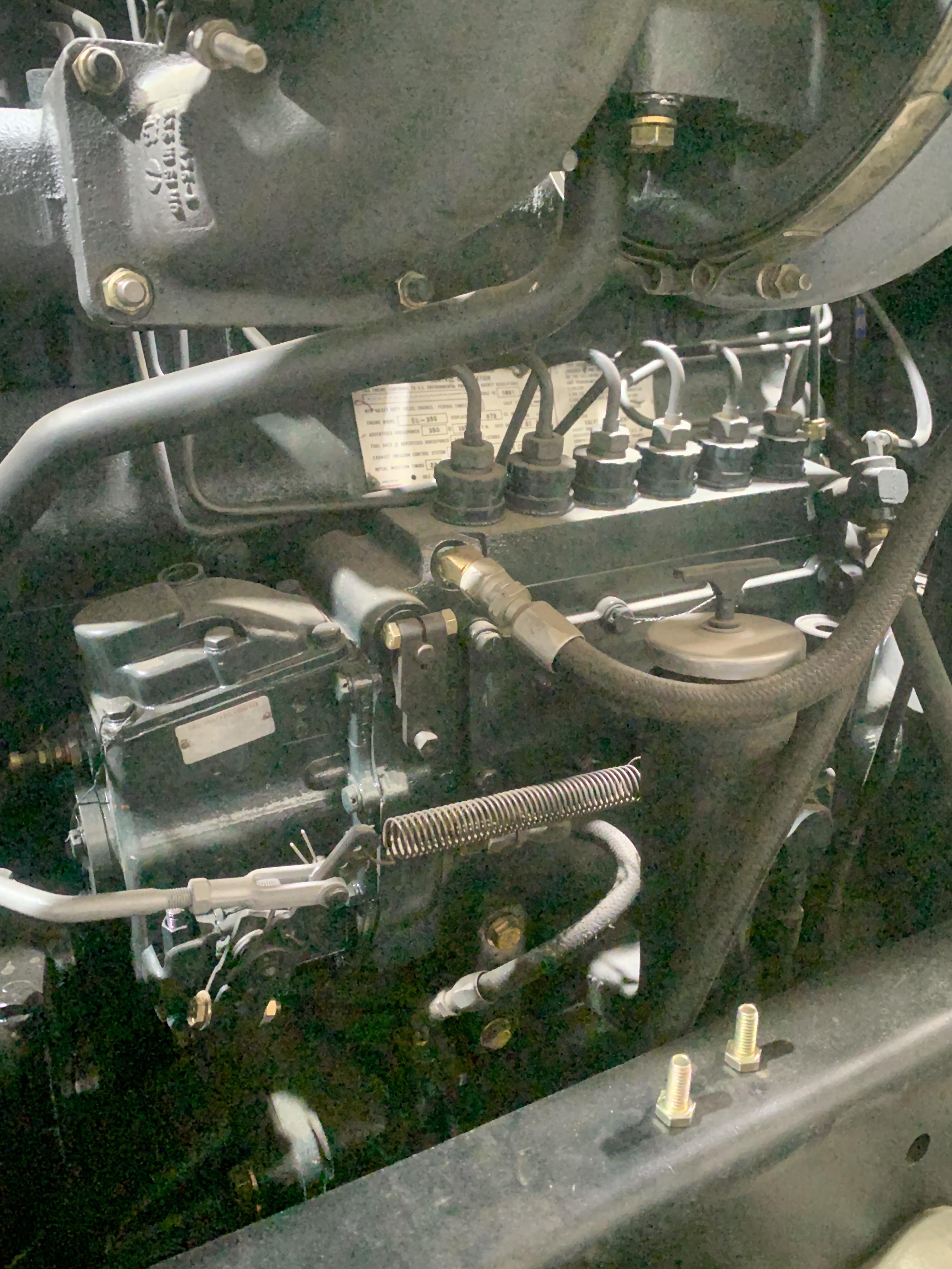
Looking through the pics I took of this engine before tearing it down and the air intake for the compressor has me scratching my head. There is a hose that comes from the head of the compressor (which should be the air intake ) but the hose goes to a fitting on the lower side of the compressor? This arrangement seems illogical to me. Can someone confirm how this is supposed to be. OK, so I can’t seem to be able to post the pic (must be too big). So that fitting that the hose goes to is just below and behind the governor bolted to a rectangle boss.
-
- Popular Post
- Popular Post
Easy enough to make. If you don’t have access to a lathe, you can get a bolt in the appropriate size and pitch, cut it to length and file or grind the slot for the cross pin. I suspect it will be ultra-fine pitch, probably 1 1/2” or there abouts. If it is some off -breed morphadite pitch it can still be easily made on a lathe. Any machine shop can easily make that if you don’t have a lathe
-
3
-
48 minutes ago, terry said:
Don’t forget you have to have your fuel return line to which tank your drawing from. Terry

👍Yes, it took some research to find a valve that has feed and return lines for each tank. Didn’t want to be drawing from one and returning to the other. 😁
-
2
-
-
1 hour ago, tjc transport said:
why two fuel gauges?
Two independent fuel tanks. I chose to go with independent tanks (no cross over) so I can manage my fuel. I am putting in a selector valve so I can choose right tank, left tank, both tanks or no tank ( isolate both tanks as an anti-theft feature, not that many would be thieves know how to drive a twin stick these days).
-
2
-
-
26 minutes ago, mrsmackpaul said:
I will have a look tonight and see what I find
Will report back
P
Thanks. If your engine dies NOT have that hose I would be interested in what it has in the two ports that this hose is useing.
-
- Popular Post
- Popular Post
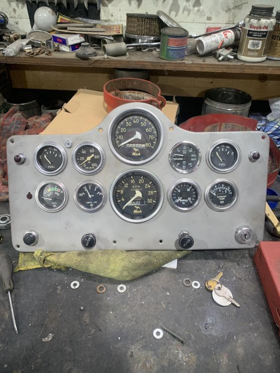
Working out the gauge cluster. Still have to seal up the headlight switch hole and relocate it 1/2” further outboard so it lines up with the signal indicator above it as well as add the engine brake switch directly opposite the light switch (I like symmetry 😁). Am going to have to add bezel covers since the gauges do not all match (particularity the dual air gauge and the boost gauge). Was wanting one more gauge (dual needle load gauge for the front and rear air bags) but have no room 😩
-
3
-
1
-
2 minutes ago, Mark T said:
The tip fan works on excess manifold pressure. You'll never even notice the little that bleeds off the manifold pressure to spin the tip fan, and the cooler air just helps overcome it anyway.
Yes, that was my point.
-
1 minute ago, Mark T said:
I don't ever remember manifold pressure bleeding off into the overboard breather. (I could be wrong)
This is a 1980 vintage E-350 econodyne. Pretty common engine so there should be someone with one that could compare. The guy I got the engine from was kinda haywire so no telling what may have been changed. I bought the engine trans (twin stick 6 speed) out of the same truck as a unit only to discover much later that the engine being an econodyne snd the trans a maxi torque that they are not compatible.
-
2 hours ago, terry said:
That line from intake manifold to downdraft tube looks like a place to lose turbo boost? terry
It certainly would (I am reasonably sure that there is no check valve or anything in the draft tube housing). However, that little line won’t bleed off anywhere near the amount of boost as the tip turbine itself. I suspect, assuming this line is as it was from new, that the turbo was/is sized accordingly to allow for the parasitic draw of the tip turbine AND that line to still provide the desired boost to the cylinders after such parasitism draws. I dunno, just postulating.
-
19 minutes ago, Mark T said:
Has that engine run with that on there ? Only other thing vented into there (at the valve covers) I ever remember was the oil filter housing.
That is how it was plumbed when pulled from the truck.


BMT Forum Logo

1965 B-53 In TENN On Hemmings
in Trucks for Sale
Posted
Perhaps you can post some pics of your truck builds to show us how it’s done? BTW, “custom” trucks (and other vehicles, like classics, hot rods, restomods and all other vehicles that are/were built to be special to the owner) often have “dry” looking grease zerks because the owned wipes the zerks clean after greasing. “Show” vehicles often get a lot more detailed attention than daily drivers or work trucks, oh, and the definition of what constitutes a vehicle worth wiping the grease off the zerks is entirely at the discretion of the owner.