
Keith S
-
Posts
392 -
Joined
-
Last visited
-
Days Won
1
Content Type
Profiles
Forums
Gallery
Events
Blogs
BMT Wiki
Collections
Store
Everything posted by Keith S
-
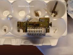
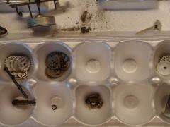
OdometerParts.JPG
Keith S commented on Keith S's gallery image in BMT Member's Gallery - Click here to view our member's albums!
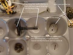 If it weren't for the drum, magnet, and drive thingies it wouldn't work.
 -
Odometer.JPG
Keith S posted a gallery image in BMT Member's Gallery - Click here to view our member's albums!
From the album: eMack Photos
-
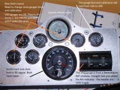
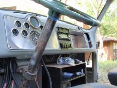
Gauges.JPG
Keith S posted a gallery image in BMT Member's Gallery - Click here to view our member's albums!
From the album: eMack Photos
-
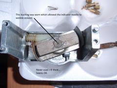
Odometer Bearing Repair.JPG
Keith S posted a gallery image in BMT Member's Gallery - Click here to view our member's albums!
From the album: eMack Photos
-
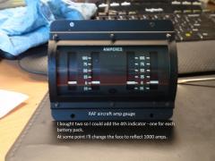
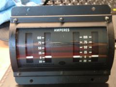
Modified RAF Aircraft Gauge.JPG
Keith S posted a gallery image in BMT Member's Gallery - Click here to view our member's albums!
From the album: eMack Photos
-
OdometerParts.JPG
Keith S posted a gallery image in BMT Member's Gallery - Click here to view our member's albums!
From the album: eMack Photos
-
Modified Aircraft Gauge.JPG
Keith S posted a gallery image in BMT Member's Gallery - Click here to view our member's albums!
From the album: eMack Photos
-
OdometerParts.JPG
Keith S posted a gallery image in BMT Member's Gallery - Click here to view our member's albums!
From the album: eMack Photos
-
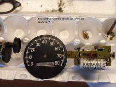
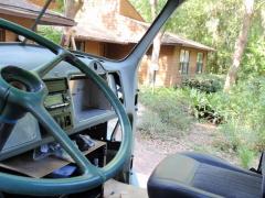
Speedometer
Keith S posted a gallery image in BMT Member's Gallery - Click here to view our member's albums!
From the album: eMack Photos
-
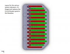
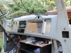
Indicator panel
Keith S posted a gallery image in BMT Member's Gallery - Click here to view our member's albums!
From the album: eMack Photos
-
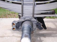
S-Cam Support and Spider misalignment
Keith S commented on Keith S's gallery image in BMT Member's Gallery - Click here to view our member's albums!
 If you're changing the support brackets I'd cross my fingers. If the chambers fit on the existing support the alignment shouldn't be worse.
 -
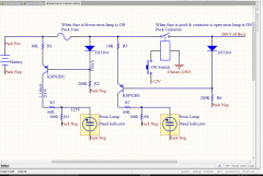
Fuse Circuit
Keith S posted a gallery image in BMT Member's Gallery - Click here to view our member's albums!
From the album: eMack Photos
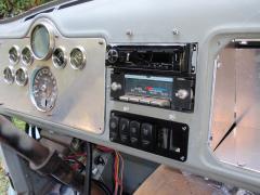
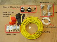
This circuit will be used to show when a fuse is blown or a battery pack contactor (relay) is open. Each of the four packs will have this circuit. There will be a indicator panel in the glove box (located where the circuit breakers used to be located). Because this is 200 volts DC, I'm using small neon lamps. Basically the circuit functions like this (ignore the resistors (R1, R2...) as they simply limit current): Pack voltage (200V) flows from the battery and hits the fuse, if the fuse is good the neon lamp circuit is ignored and voltage flows to the Pack Contactor. If the Pack Contactor is open (turn off), transistor KSP92BU (in the middle) acts as a switch and turns on the neon lamp If the Pack Contactor is closed (turned on), the circuit is ignored and neither neon lamp is on. If the fuse is blown, transistor KSP92BU (on the left) acts as a switch and turns on the neon lamp. The Pack Contactor neon lamp will be off - which is not really correct because that means the contactor is closed which may not be correct. So I may change the circuit and move the R5 connection to the Battery side of the fuse. -
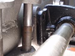
Spider and S-Cam Alignment
Keith S commented on Keith S's gallery image in BMT Member's Gallery - Click here to view our member's albums!
 Removing the spider was super easy - just loosened the bolts. Checked the S-Cam bore for squareness with the base and it was fine. So, I'm not thrilled with this idea, but I'm seriously considering: Replace the 5/8" bolts with 9/16" gr8 - that gives enough rotational slop to allow the s-cam to nicely align. Drill and ream two 5/8" holes through the spider and backing - top and bottom in picture. Press in two 5/8" stainless steel dowel pins to keep spider from rotating. The dowel pins are to keep the spider from rotating because of the bolt slop. Then tighten the hell out of the gr8 9/16" bolts. What do you guys think?
 -
eMack Photo Album at: http://photos.advanced-ev.com/
Keith S commented on Keith S's gallery image in BMT Member's Gallery - Click here to view our member's albums!
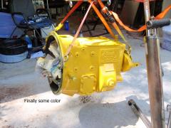
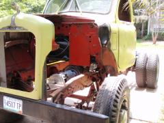 It does looks small. It's a Warp11 (11.75" diameter) DC series motor. With electric motors, torque is the big thing. Motor torque is based on how amps you can push through it. Motor HP is based on how much voltage you push through it. Cruising you need HP; accelerating you need torque. This little motor's torque (at 1,800 amps) is about 550lb-ft from 0-1500 rpm. Those are dyno numbers, but not reality. I'm limiting this motor to 200 volts, and 1000 amps. Unless I floor the accelerator while in 4th or 5th gear, it'll never hit 1000 amps. Max amps will probably spike at 750 amps for a fraction of a second. Range: With stop-and-go driving I should get around 130 miles. Highway cruising range (55-60 mph) will be much less - I'll be surprised and really happy to get 80 miles.
 -
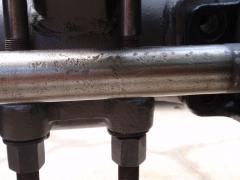
Sign of some problems to come?
Keith S posted a gallery image in BMT Member's Gallery - Click here to view our member's albums!
From the album: S-Cam Repair
Someone had a bad day with this s-cam -
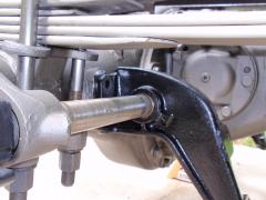
S-Cam Support and Spider misalignment
Keith S posted a gallery image in BMT Member's Gallery - Click here to view our member's albums!
From the album: S-Cam Repair
So this is why this S-cam was ground and beat on. -
Cast iron (steel?) Spider
Keith S posted a gallery image in BMT Member's Gallery - Click here to view our member's albums!
From the album: S-Cam Repair
-
Spider and S-Cam Alignment
Keith S posted a gallery image in BMT Member's Gallery - Click here to view our member's albums!
From the album: S-Cam Repair
OK. So my questions are: How much slop is there in the spider bolt holes? It looks like if there is enough slop, I could rotate the spider and align (I hope I hope) the s-cam. Everything is machined, so where is the S-Cam's "alignment adjustment"? If I replace the spider, how is the spider aligned with the s-cam support? Anyone have part number for a replacement spider? -
Hmm...
Keith S posted a gallery image in BMT Member's Gallery - Click here to view our member's albums!
From the album: S-Cam Repair
Lots of things wrong in the picture -
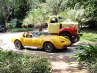
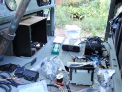
From the album: eMack Conversion
I started putting together an on-line eMack photo album. Nothing technical, just pictures for now. It's located at: http://photos.advanced-ev.com/ -
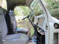
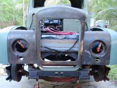
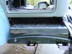
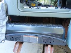
eMack Conversion
Images added to a gallery album owned by Keith S in BMT Member's Gallery - Click here to view our member's albums!
How to convert a Model-B Mack truck to all electric power. -
-
KD 517 Cab lights
Keith S replied to Keith S's topic in Antique and Classic Mack Trucks General Discussion
That's an interesting part number - it brought up a whole bunch of "equivalents". Specifically the DO-Ray 410's, which led to a whole bunch of truck cab lights. Anybody know about the DO-Ray 410? -
My Model-B 46 came with five good KD517 bezels and amber lenses. What I don't have are the bases. Has anyone hacked-to-fit any of the new el-cheapo teardrop plastic cab lights to fit the KD517s? At $23 for five el-cheapos, it doesn't seem like too big a waste of money if it doesn't work. I've wasted more than $23 on a lot of stuff/ideas that didn't work!
-
Proof of Concept for S-Cam repair
Keith S commented on Keith S's gallery image in BMT Member's Gallery - Click here to view our member's albums!
 I used to grind crankshafts and considered having it welded and then ground. If it was someone else's money, I might. But, there are two journals on each S-cam and a lot of heat is generated during welding journals. My biggest concern with welding and then grinding the journals is that I don't know anything about the hardening and heat treating used on the S-cams. There was several ways I could have "repaired" the s-cams. The epoxy approach was Plan A. It was the least destructive to the base material. The epoxy was $45 and claims to be suitable for repairing this type of bearing. If this stuff flakes off I can always get more aggressive/destructive with grinding then sleeve it - still no loss of base "hardening". The last and most aggressive/destructive of the original part is grinding, welding, then grinding again.
 -
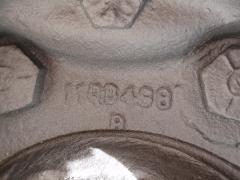
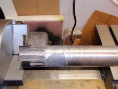
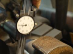
Finished size - 1.498
Keith S posted a gallery image in BMT Member's Gallery - Click here to view our member's albums!
From the album: S-Cam Repair
I think the finished size should be 1.500". The bushings are 1.505" bore w/o press-fit into spider. Should fit well - much better than it was. It's not as good as new, but...


BMT Forum Logo
