

Full Floater
-
Posts
367 -
Joined
-
Last visited
Content Type
Profiles
Forums
Gallery
Events
Blogs
BMT Wiki
Collections
Store
Posts posted by Full Floater
-
-
Im wondering now if one of the dogs got out of whack when installing the center disk of the clutch. there was no slop in there had to give it a push to get the disk on.
-
The engine is a 235 and trans is a 107 six speed in both trucks. Same flywheels, different model trucks. Both had mechanical clutch linkages with a cable from the pedal. but slightly different linkage setup at the bellhousing, so that's a difference. The new clutch looked the same as the clutch that was in it, the numbers off the old clutch were cross referenced to the new clutch. I didn't mess with the dogs. What tool is there to align them? Yes the clutch brake is on the trans input shaft. It's a Babcock 2 piece. Same that was in there.
Ya so the main symptom here, just so I stay clear in my ramblings; is the clutch will not disengage while the engine is running, to allow the transmission to be placed in gear. I installed the clutch on the flywheel/engine while the engine was on the ground being overhauled. It installed into the truck pretty flawlessly. Anti rattle "shims" were installed as per instructions in the clutch kit. I was new to those but I don't think they would be causing my grief.
Im thinking the issue must be internal. Im hoping its just a sticking clutch disk that I can free up somehow, I just can't really drive it at the moment to free it up buy rough housing it a bit.
I will take a pic and post it here so there can be a visual.
-
 1
1
-
-
The engine starts and runs no problem.
With the engine running, when I depress the clutch to the floor to wait a couple seconds for the clutch brake to do it's thing, I cannot get it into gear, it just grinds as if im trying to stab it into gear without pressing the clutch in. I can wait a long time with my foot to the floor, and still no engagement, it just wants to grind.
-
I let the local heavy truck jobber source the clutch for me....sure hope they gave me the right one.
-
I can put the truck in lo gear and start it but it's not currently in a position to move more then a few feet. And I have the service brake system all apart for new relay valves and such. It did actually jump into gear when I was trying it and had to pull the shut down to get it to stop as I had no clutch disengagement to take the load of the trans to get it out of gear. Didn't have room to throttle it and release, to brake the torque.
I have had someone work the clutch as I watched, the throw out bearing pulls the clutch "rod" back and the bearing moves up against the clutch brake. Also used a board for adjusting purposes to hold the pedal down when nobody was around.
One thing I cannot do, or I haven't yet, was to measure .010" gap at the clutch brake with the pedal at the floor as I can't get in there with the Mack style release fork in the way. Will have to custom bend a feeler gauge or something. But it's probably close enough that I should get at least marginal disengagement
Yes the clutch plates went in right. Triple checked that when installing.
The release fork is on the right side of the throw out bearing hahaha. I can see how THAT problem could potentially occur
-
3 months later, getting back to it, the clutch is adjusted with 1/2'' +/- between the throw out bearing and the new clutch brake, pedal free travel about 2''
I cannot get the clutch to disengage even if I adjust +/- on the kwik adjust and/or linkage. I've tried adjusting it both ways and adjusting the linkage several times, to no avail. Everything is adjusted to spec again before I move on. The trans just grinds as I try to put it into gear and will not mesh. The clutch discs went in the correct way, line up tool used to align it and new pilot bearing. The clutch brake is new
Could it be that the clutch plates are stuck to the re-surfaced flywheel from sitting a few months? Can I rap on the back of the clutch through the inspection hole to attempt to free it up? If so, should I do that with the pedal depressed?
-
2 hours ago, Joey Mack said:
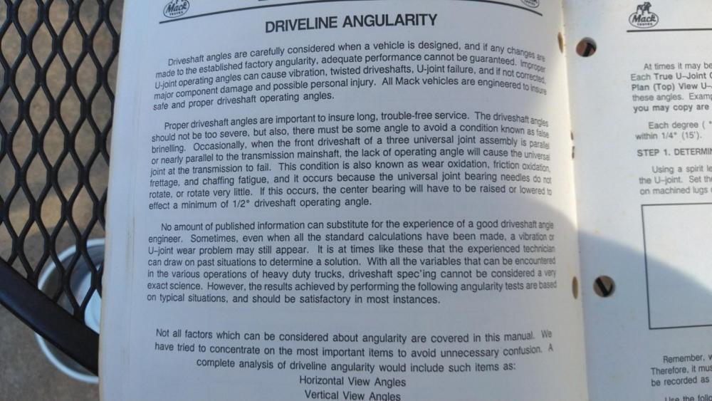
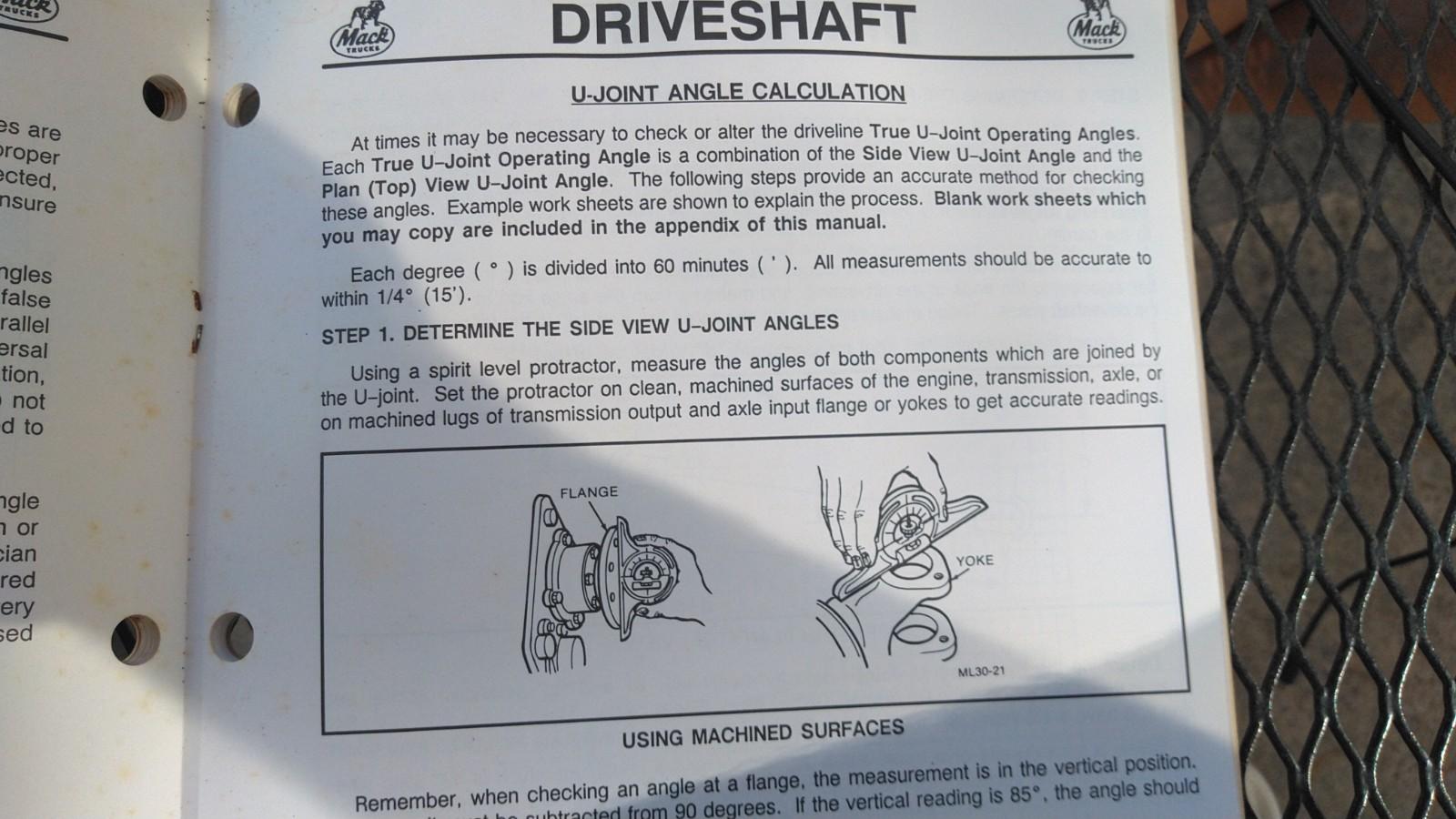
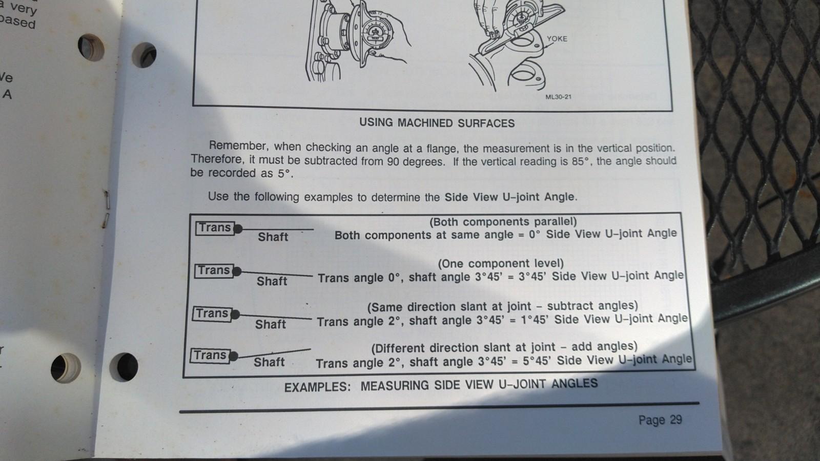
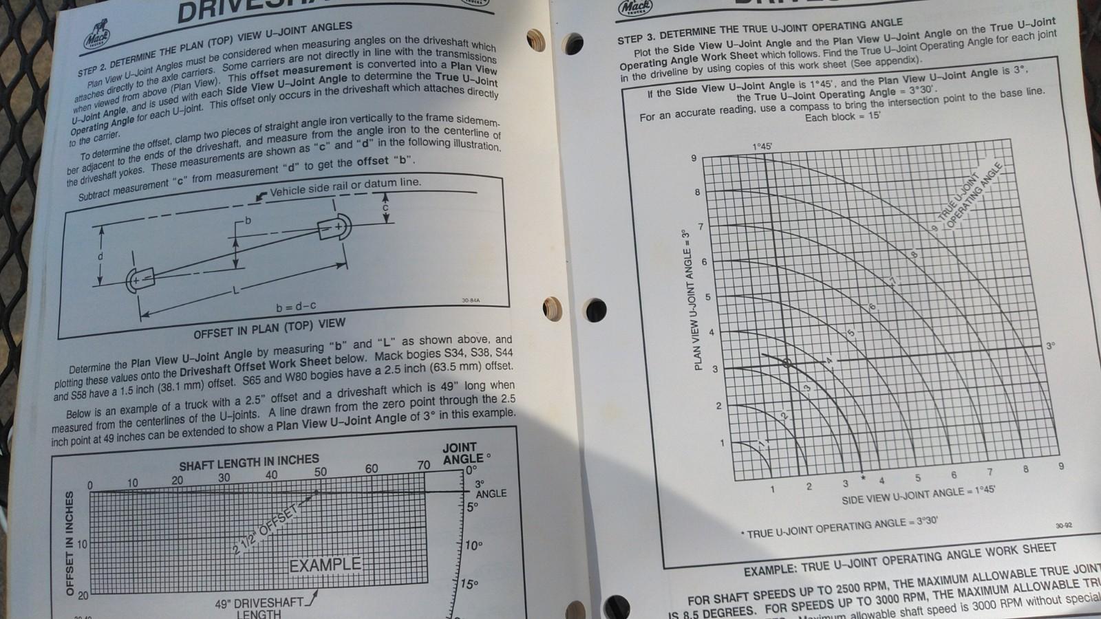
Ok,, I have this book. Here is what I think you are asking for.. Text me if you cant read it clearly or for whatever reason. 704-785-1738


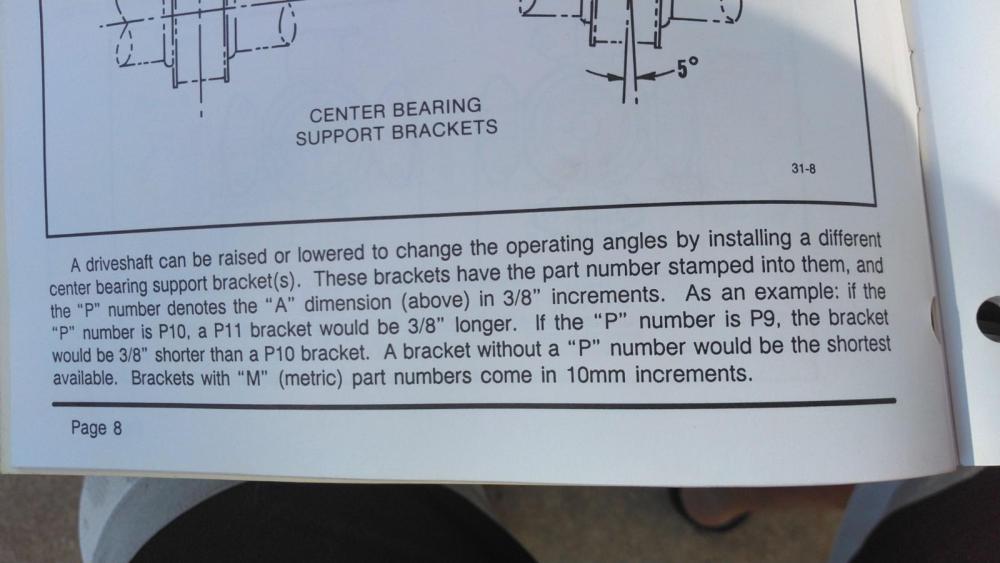


A reply that exceeded all expectations, again!
THANKS
-
1
-
-
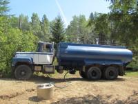
I am in the process of converting a tandem R600 into a single axle for a re-purpose of the truck.
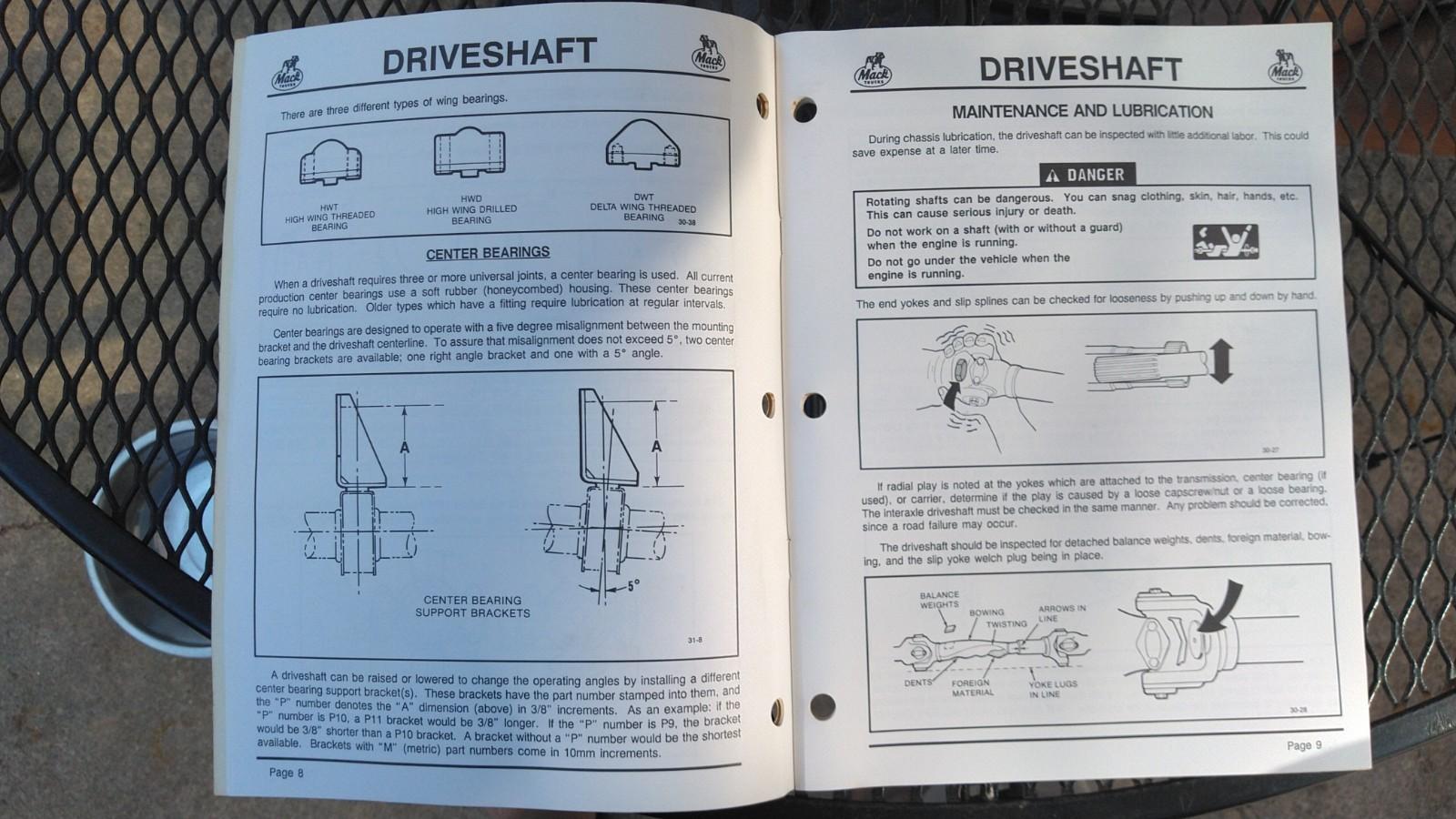
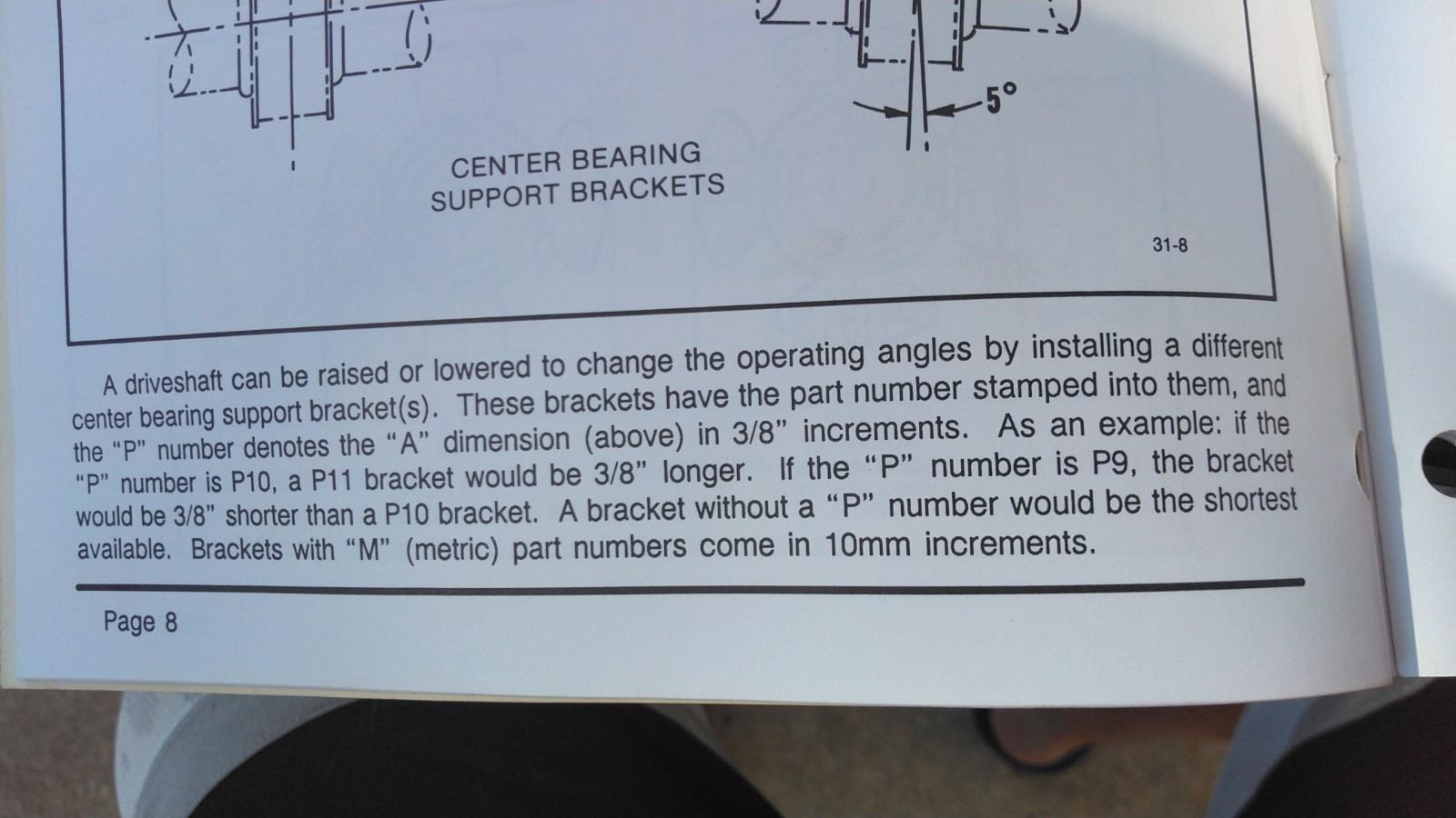
The overall length of the driveshaft has extended by a little over 2ft. I had the driveshaft professionally lengthened and balanced. All new u-joints and steady bearing. The location of the steady bearing is further back and I am moving a crossmember to accommodate the bracket. AND I have to use or make another steady bearing bracket as I didn't get the bracket back with the driveshaft and the driveline shop is 5hrs drive away.
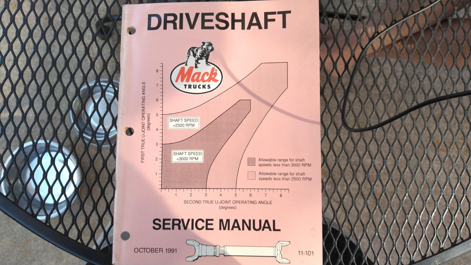
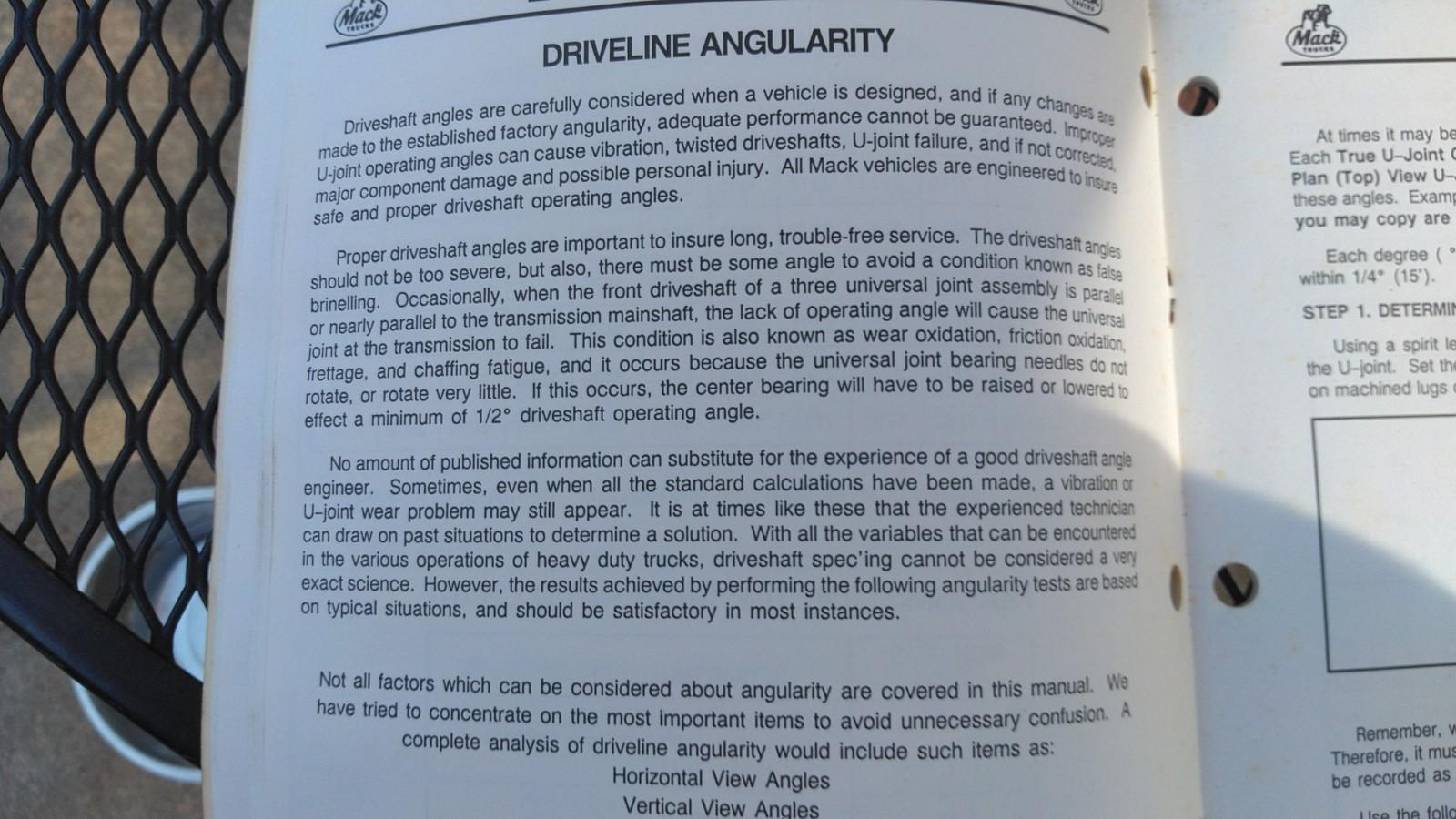
Can someone school me on driveshaft angles a bit? It's my understanding that the angle of all the joints should be 3 degrees or less.... what else am I missing here?
-
On 6/6/2023 at 7:06 AM, 1wonton said:
Thanks Jeff, pulling a long hill the gauge does get up to that but for not very long. I guess that's ok?
You're pyro probe is in the downpipe after the turbo and not in the manifold, correct?
Ya don't hold it at those temps for too long.
-
1 hour ago, MACKS said:
With the rear mount u don’t have to put the Tran in gear with splitter In neutral ,it works in neutral and also when in gear your body will go up just as fast even if your in first gear,great for running out loads..
Ah good to know!
-
I just bought another parts truck, with a 6 speed and a side mount with a driveshaft pump. Never actually seen a side mount on a 6 speed. Haven't got the number off of it, just something I noticed
-
On 6/3/2023 at 2:38 PM, MACKS said:
Rear mount pto to remote pump is your only option,get it set up right keeping the drive shaft as short as possible,still way better than a side mount..
Thanks.
Curious as to what is better about the rear mount? Is it a stronger or more reliable location to mount the PTO, rather then the side?
-
Thanks. So all the delivery ports are the same, and all the supply ports are the same, correct? Just a matter of where the line and fitting fits best?
-
 1
1
-
-
1 hour ago, mechohaulic said:
it should unless that's another example of modern day cut backs. might be there just written in foreign language; or maybe no words just pictures for todays border crossers.
Exactly. Prime example of cutbacks. Made in China for sure
-
 1
1
-
-
I think figuring out which port is supposed to deliver air to the foot valve, would get me going as I would then be able to see which port exhausts air when the pedal is depressed for the front service brakes, as for the rear maxi's, I suppose there would also be air at that port for the foot valve to "release" to apply service brake to the rear
-
58 minutes ago, mechohaulic said:
one other advantage of the days with copper lines; valve proper position , air lines if not bent would line up. port size would place them close also. plastic a different deal.
Definitely.
I avoid plastic/nylon lines when I can and try to stick with fabric braided lines and JIC style fittings.
-
1
-
-
It actually doesn't, but I got a diagram on the www.
Such as this one
http://www.newtruckspring.com/wholesale/bendix-277863x-e-3-brake-valve/
-
Picked up a 76 600 western that runs and drives but the owner died a few years back, however; the foot valve is out of it, with a new Bendix E3 sitting on the floor to replace it with. Im wanting to install it on the spot so I can drive the truck home.
I've always just placed the old lines on to the new foot valve as they came off the old valve, not really know which port is supposed to do what. Can't do that with this one as the old valve is gone.
-Does the supply air for both front and rear service brakes come from the "delivery" or "supply" ports on the foot valve?
-Also, which port is supposed to supply air to the foot valve itself?
This should steer me in right enough direction to get me going without too much crossing lines.
-
7 hours ago, MACKS said:
Why not use a speedy sleeve,that’s what there for and u can use the same seal as without the sleeve.just asking..
Not a smaller ID seal needed when running a speedi sleeve?
-
I have yet to speak with a drivetrain shop to see what they might know of, as to what's out there or what can be made.
-
On 5/29/2023 at 7:05 PM, b61fred said:
Well I removed the governor and found the culprit! The internal shaft on the throttle was worn just enough to slop around. I made a video on YouTube to describe what was wrong and what I done to fix it if you want to see.
thanks for all your help.Awesome! Thanks for sharing the video and your findings. Can't wait to watch it.
-
1
-
-
I notice this on all my Mack E6's. The gov springs in general seem to be a weak link on these and can be very touchy. I bet the slight load, or lack there of it when the compressor is off, throw the gov springs off slightly.
I wouldn't worry about it much, although it can be a bit annoying.
But hey, it's way better then a new truck with a check engine light
-
 1
1
-
-
5 hours ago, Full Floater said:
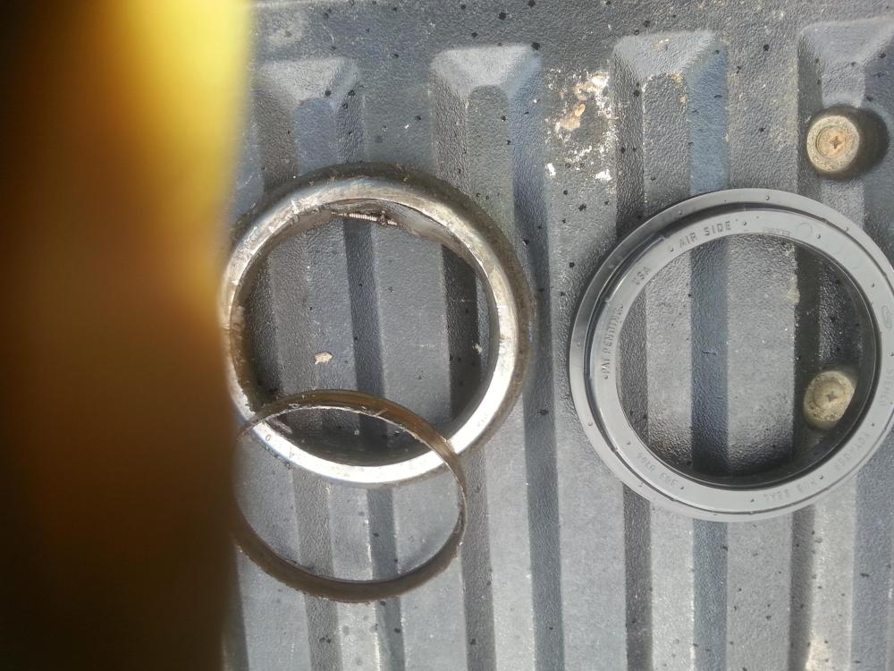
Yes, I'll take some pics. The Stemco number is 320-2137, crosses to a Voyager 383-0164. I did manage to find some early seals at Finditparts online and ordered them for on the shelf for later. But the Voyagers are the only thing I can get here locally at any of the jobbers
Stemco 2 piece vs Voyager. The voyager went in nice and smooth and seemed to fit well. Running Lucas Hub oil. Will see how it lasts.
-
1
-
-
3 hours ago, Joey Mack said:
can you clean the old seal and post a picture of it and the seal number??? If I can get info I will post it for you.. Hell, i'll buy the seals and send them to you..
Yes, I'll take some pics. The Stemco number is 320-2137, crosses to a Voyager 383-0164. I did manage to find some early seals at Finditparts online and ordered them for on the shelf for later. But the Voyagers are the only thing I can get here locally at any of the jobbers
-
1
-

BMT Forum Logo

235 Swap
in Engine and Transmission
Posted
Tomorrow I might try blocking up the rear axle and run it thru some gears and jar it with the throttle a bit