


FireSKip17
-
Posts
19 -
Joined
-
Last visited
Content Type
Profiles
Forums
Gallery
Events
Blogs
BMT Wiki
Collections
Store
Everything posted by FireSKip17
-
The cable for the RPM tachometer is broken where it goes from the engine block right side to the splitter on the left frame rail engine compartment. I was curious if anyone had a lead on where to find a replacement for this. I pulled one from a donor truck but realized it's a foot shorter.
-
EN464 fuel pump
FireSKip17 replied to b422's topic in Antique and Classic Mack Trucks General Discussion
I got to rebuild kit from then and now out of Massachusetts. I plan to do that next week -
EN464 fuel pump
FireSKip17 replied to b422's topic in Antique and Classic Mack Trucks General Discussion
Ultimately mines a EN707, but it has this AC fuel pump on it. I emailed Terrell Machine awhile. -
EN464 fuel pump
FireSKip17 replied to b422's topic in Antique and Classic Mack Trucks General Discussion
where did you find a kit? Im about to reach out to daytona -
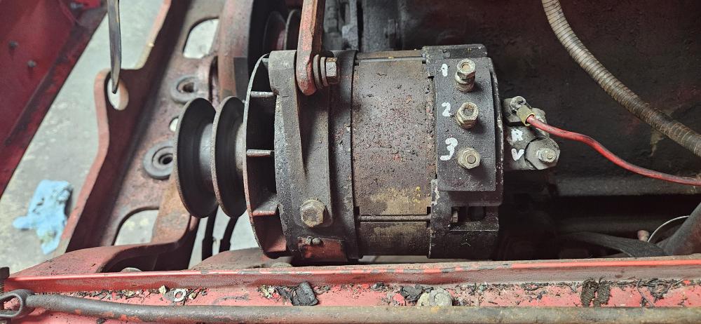
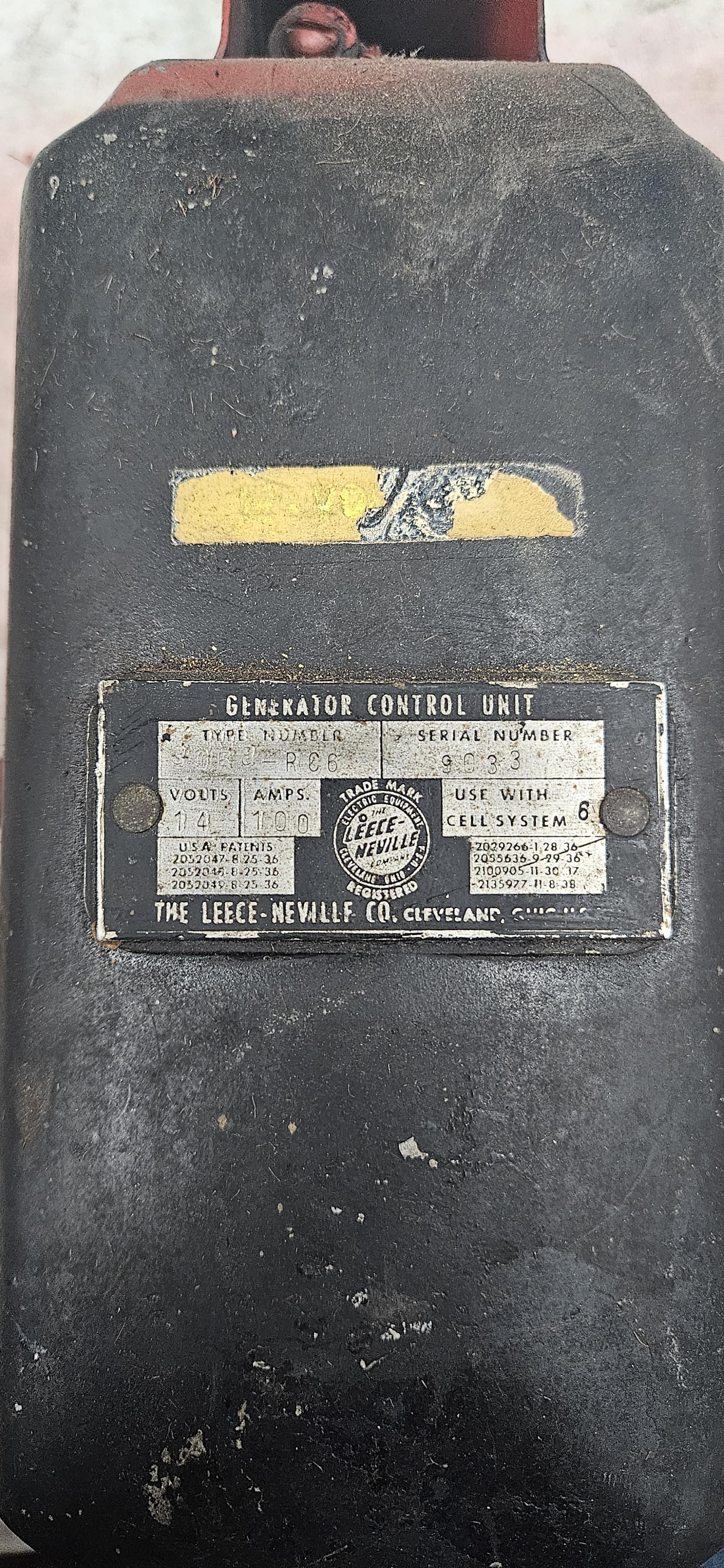
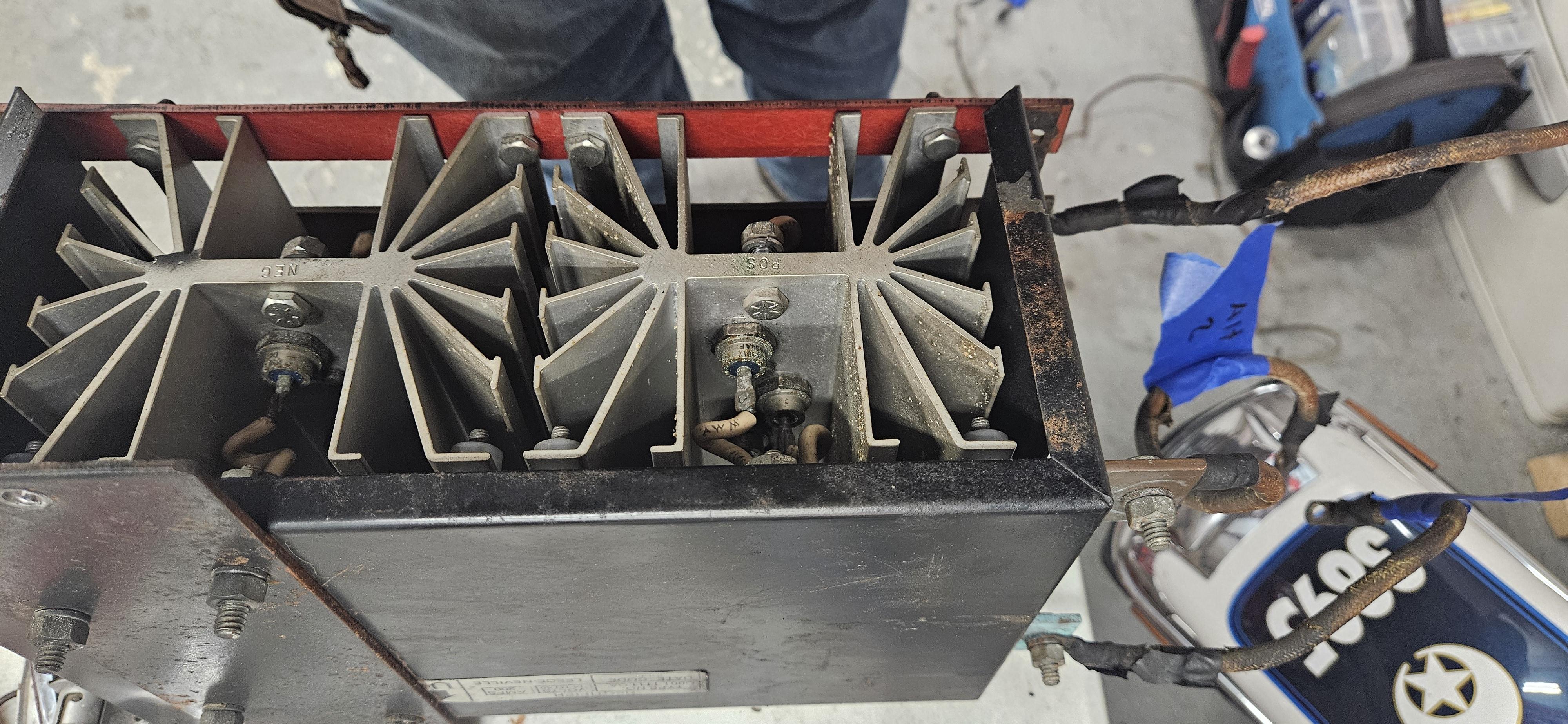
We had multiple wires frayed, currently re-wiring the truck. The Amp meters both always read 0. Drove it an hour tho and it didn't die, so maybe it works. So can't truly confirm it's function. The one bar marked AC is heavily blued tho. Wouldn't want to switch the grounds around tho bc the radio and siren are specifically 12v POS.
-
Here's how ours was setup with 12v positive ground: -Battery Selector switch to "B" on voltage regulator. -Left Ignition Switch to "IGN" on voltage regulator. -"G" on voltage regulator to "NEG" on rectifier. -"GND" on voltage regulator to "POS" on rectifier. -"F" on voltage regulator to rear field post of Alternator. -the top post of the voltage regulator grounds to the mount/firewall. -the 3 larger posts on the alternator (phases??) went to the long 3 bars on the rectifier, they are marked "AC" on mine. - the other rear alternator post, I assume another field, goes to the "POS" on the rectifier. I'd love to get rid of all this and go single wire alternator.


-
I have mine all pulled and mapped out. I'll share Saturday next time I'm messing with it how these fire engines are wiring with the rectifiers. I am looking to swap the system out to a 1 wire alternator tho.
-
If someone wanted to swap to a newer 1 wire alternator, any suggestions on an easy drop in? I'd love to get rid of the rectifier and voltage regulator on this Mack
-
Which diagram is it? The 51 L85 I'm messing with needs 8mr 4140 but all I have is 4929 to reference.
-
1941 Mack A40 Magnadyne idle issue
FireSKip17 replied to FireSKip17's topic in Engine and Transmission
I get no difference with the air cleaner on -
1941 Mack A40 Magnadyne idle issue
FireSKip17 replied to FireSKip17's topic in Engine and Transmission
Thanks. I'll drop an inline gauge on the fuel line but I feel it's good. I'll pull the governor and see what I can find. I absolutely soaked the intake manifold and got nothing. -
1941 Mack A40 Magnadyne idle issue
FireSKip17 replied to FireSKip17's topic in Engine and Transmission
No vacuum advance -
1941 Mack A40 Magnadyne idle issue
FireSKip17 replied to FireSKip17's topic in Engine and Transmission
I'll check the carb butterfly's. The idle screws are set to 1.5 turns. I unhooked the vacuum line and plugged it to eliminate the possibilities of leaks in the vacuum system. Could the governor play any part in this issue? -
1941 Mack A40 Magnadyne idle issue
FireSKip17 replied to FireSKip17's topic in Engine and Transmission
That was my thought too. But we stripped and had the carb rebuilt. Adjusting the idle mixture screws doesn't seem to do anything. -
1941 Mack A40 Magnadyne idle issue
FireSKip17 replied to FireSKip17's topic in Engine and Transmission
I sprayed carb cleaner all over it and couldn't get any rpm changes. Was frustrating. I soaked the back of the carb and the top half of the manifold where it bolts to the block -
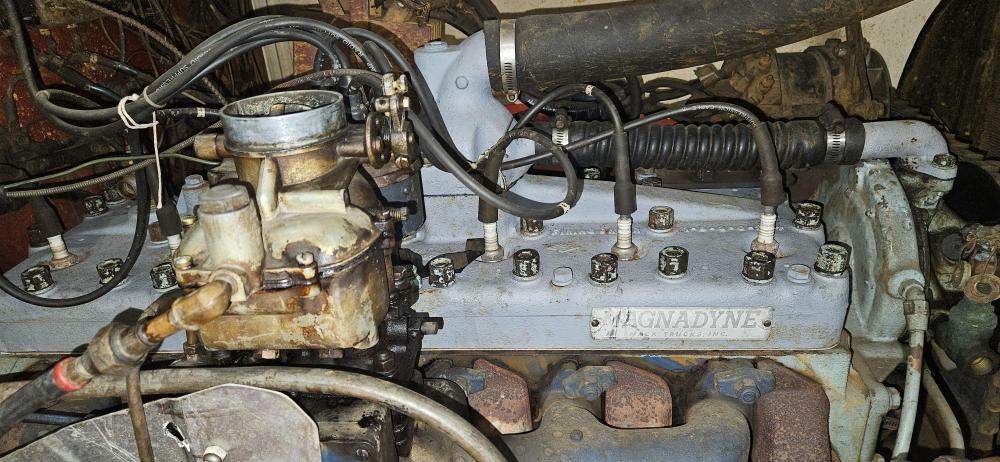
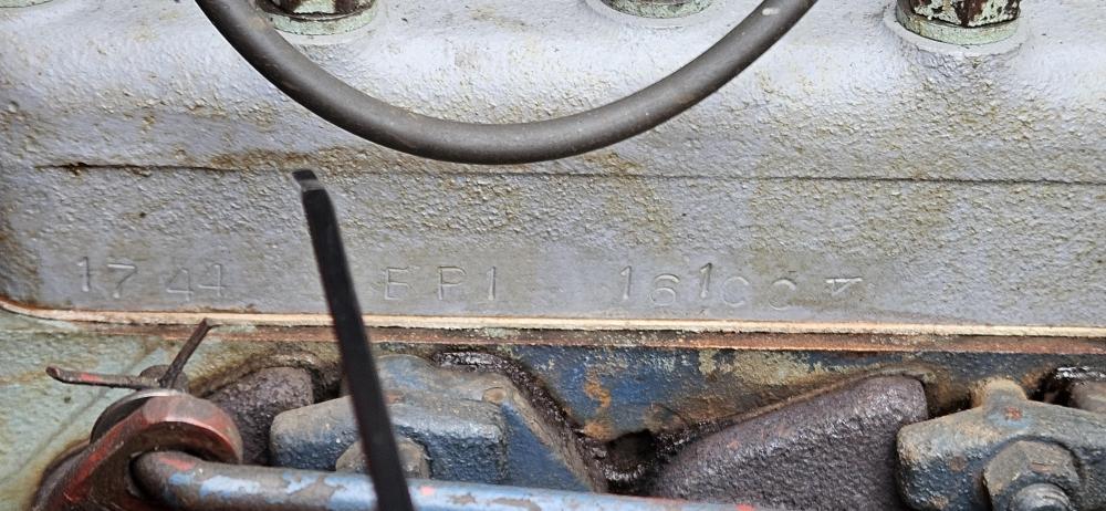
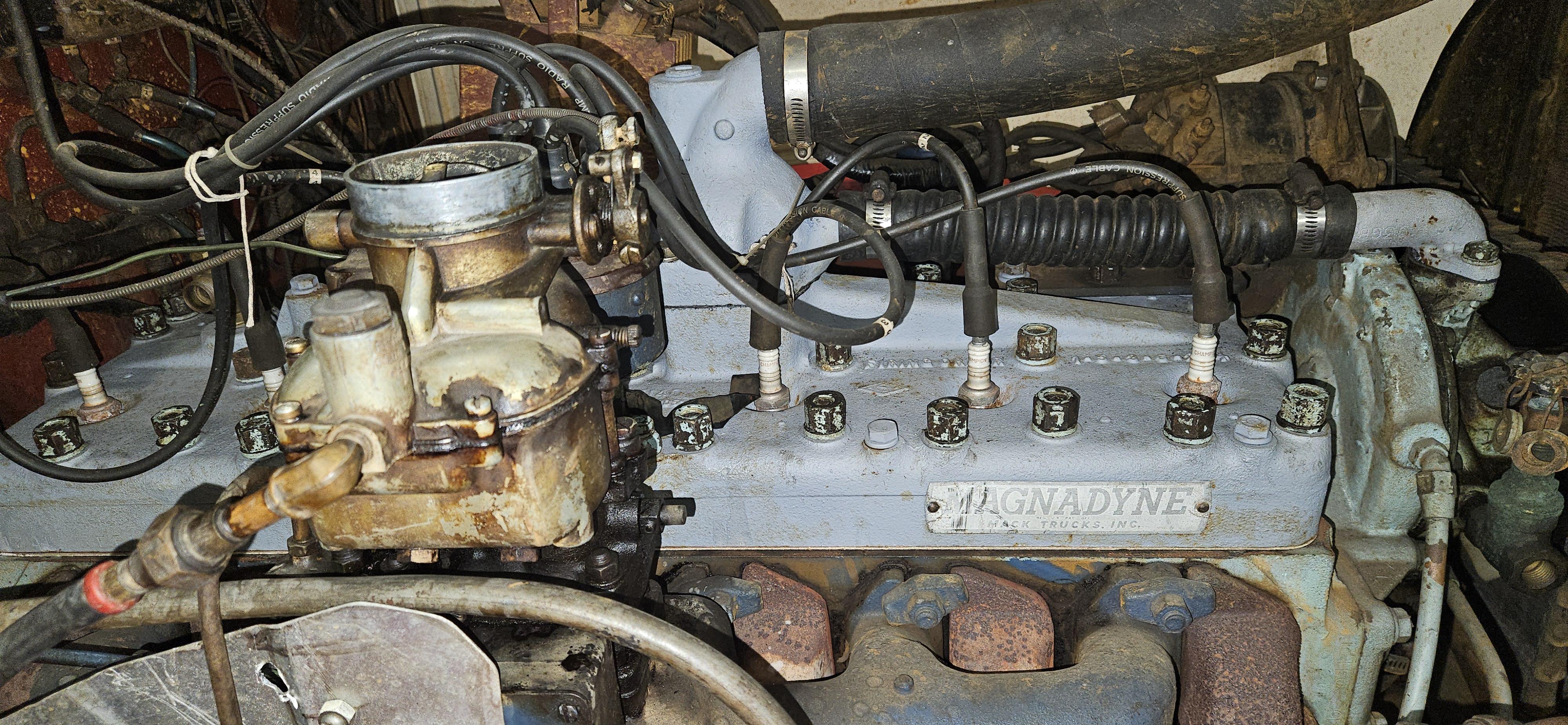
Helping a friend with an antique fire engine. I can not tell what size this Magnadyne engine is, attached are photos of the block stamping. We can not get it to idle with the choke off. Will only run with half choke or with a 1/4 or more throttle. Had the carb rebuilt. Going to do the ignition system next. Slowly been burning out the old gas to try fresh fuel. I disconnected the vacuum line first thinking a leak but that did nothing. Sprayed down the intake manifold with carb cleaner to listen for an engine change but nothing. Only adjustments I can see on the carb are the 2 idle mixture screws and that's made no difference either. As soon as you put the choke in and off the throttle it dies. Any thoughts on what else I maybe missing.? What is the device between the carb and the manifold, I assume some type of governor?
-
1951 L85 Rear Spoke Wheel rebuild question
FireSKip17 replied to FireSKip17's topic in Driveline and Suspension
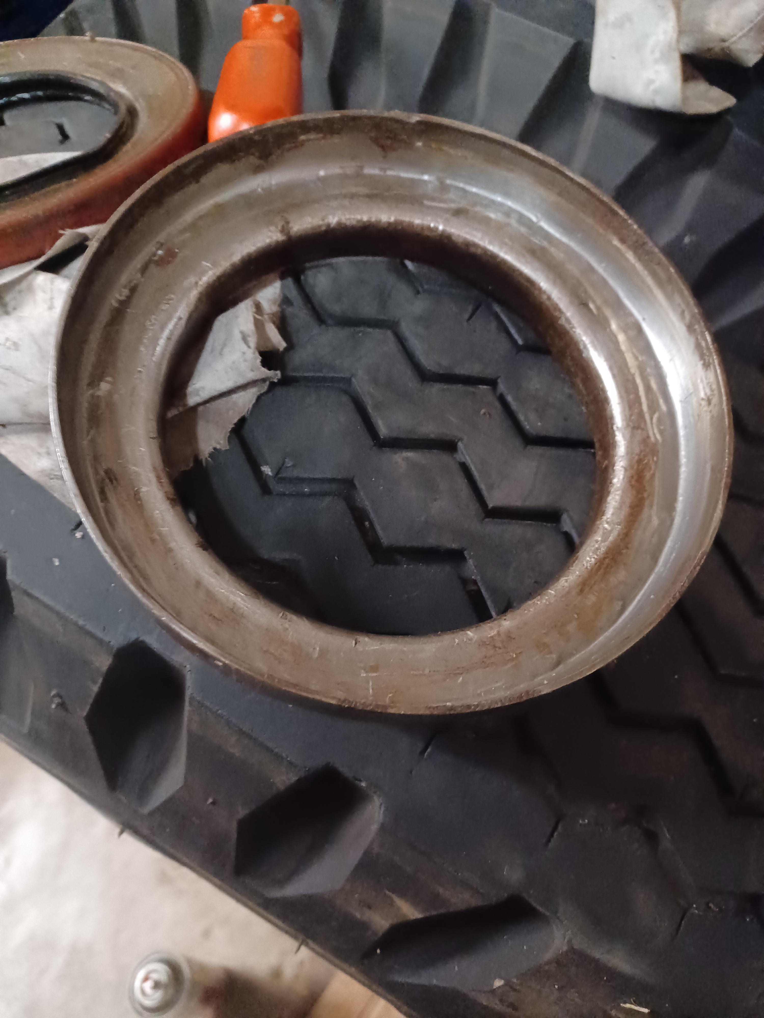
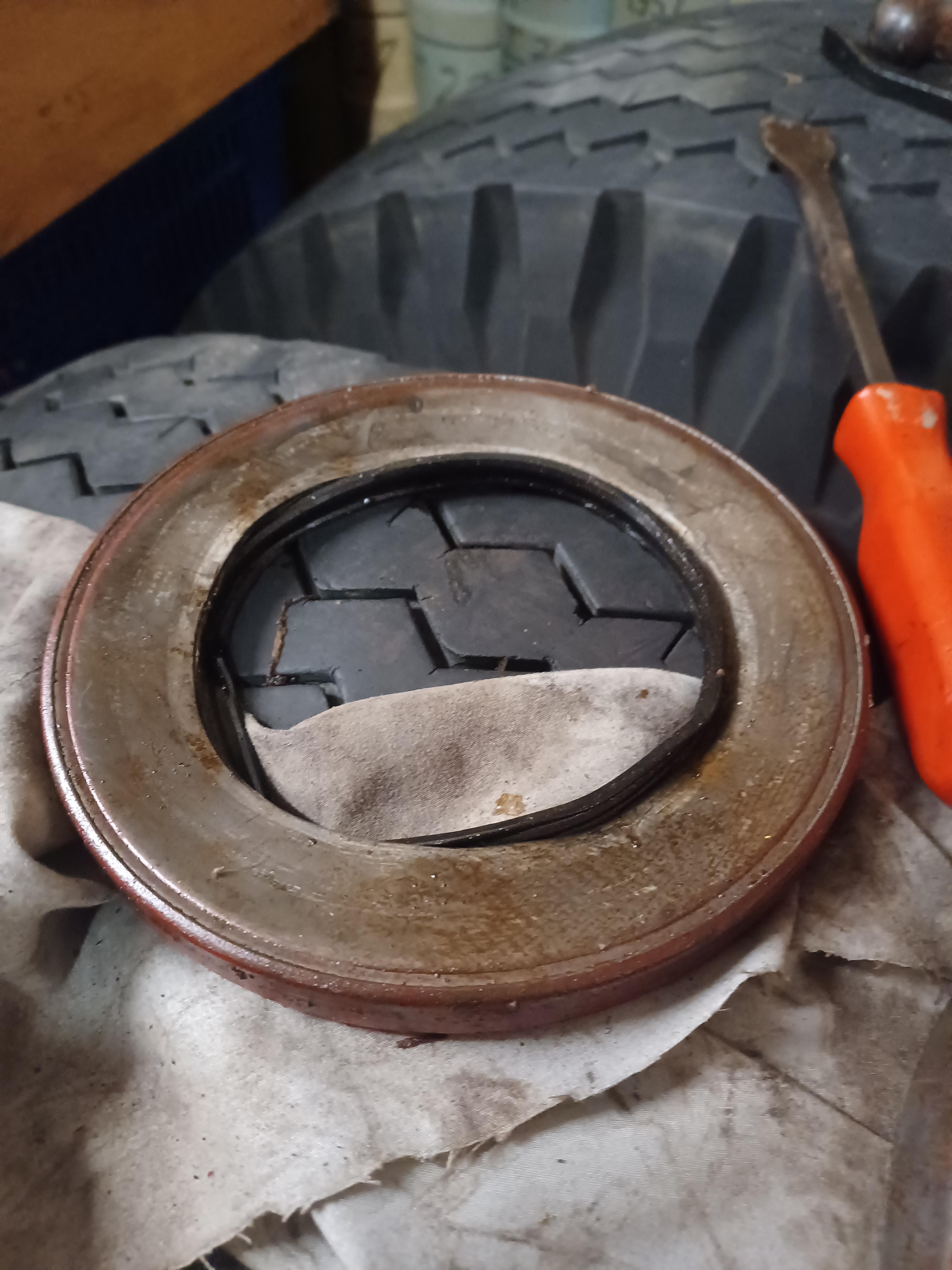
I got more photos from my friend. This orange ring that was on the back of the hub was pressed on. It has no signs of contacting the axle or spindle at all. The seal was then inside this then pressed into the hub.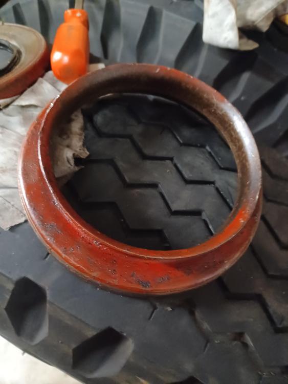


-
1951 L85 Rear Spoke Wheel rebuild question
FireSKip17 replied to FireSKip17's topic in Driveline and Suspension
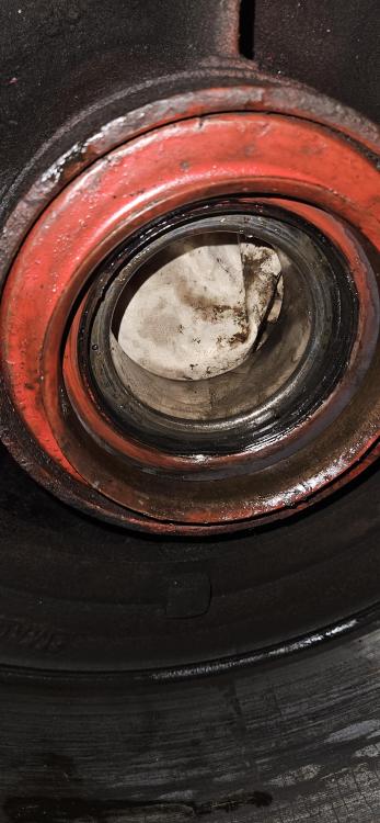
We have a new inner bearing and both seals. Plan on grease packing the bearing. My question is how to place the center seal properly. The photo is from the inner side of the hub -
Hello everyone. I'm helping a friend get a newly acquired 1951 L85 Fire Engine back on the road. Just replaced the rear wheel cylinders to finish off all knew brake parts, and wanted to rebuild the rear spoke hubs while they are off. Couple questions because I've personally only ever done regular hubs never spoke Daytons. Is this red ring on the inside a dust cover? We popped everything out using a drift thru the hub and notice the seal and this ring are separate. Any diagram or insight on how this "should be". What's the best way to press it back in then once the new bearings and inner seal are set? I assume there was once a special tool. Also, I know some people remove the middle seal and allow the axle gear oil to lube the inner bearing, but if one were to want to stay traditional and grease pack it does the race need removed in order to set that middle seal? Thank you


BMT Forum Logo
