


rhasler
-
Posts
1,907 -
Joined
-
Last visited
-
Days Won
54
Content Type
Profiles
Forums
Gallery
Events
Blogs
BMT Wiki
Collections
Store
Everything posted by rhasler
-
I haven't personally seen any, but the Bendix website would probably be the place to look for info. I believe they are the manufacturer of the currently hyped setup. The older ones were Rockwell/Meritor. I would think the biggest factor would be parts availability. If no one else in your area, or the areas you run in, uses disc brakes I would expect that there would be a wait for parts when it came time to replace pads or discs. Keep in mind that the fewer trucks with this setup the less likely you are to find someone able to work on them correctly, and low parts availbility means parts that need to be replaced don't get replaced sometimes. I would hate put my life on an expensive brake system that I wasn't sure had been fixed correctly!
-
I haven't had much experience with them either. I think the main problem with them was the bolts in the later version that used bushings would break. The fix was to line ream the axle housing hanger bracket eyes so that 1" bolts could be used instead of 7/8" bolts. Mack has a newer suspension the "M Ride" that is kind of similar to this. I think it's actually a Volvo design used priamrily on the VHD.
-
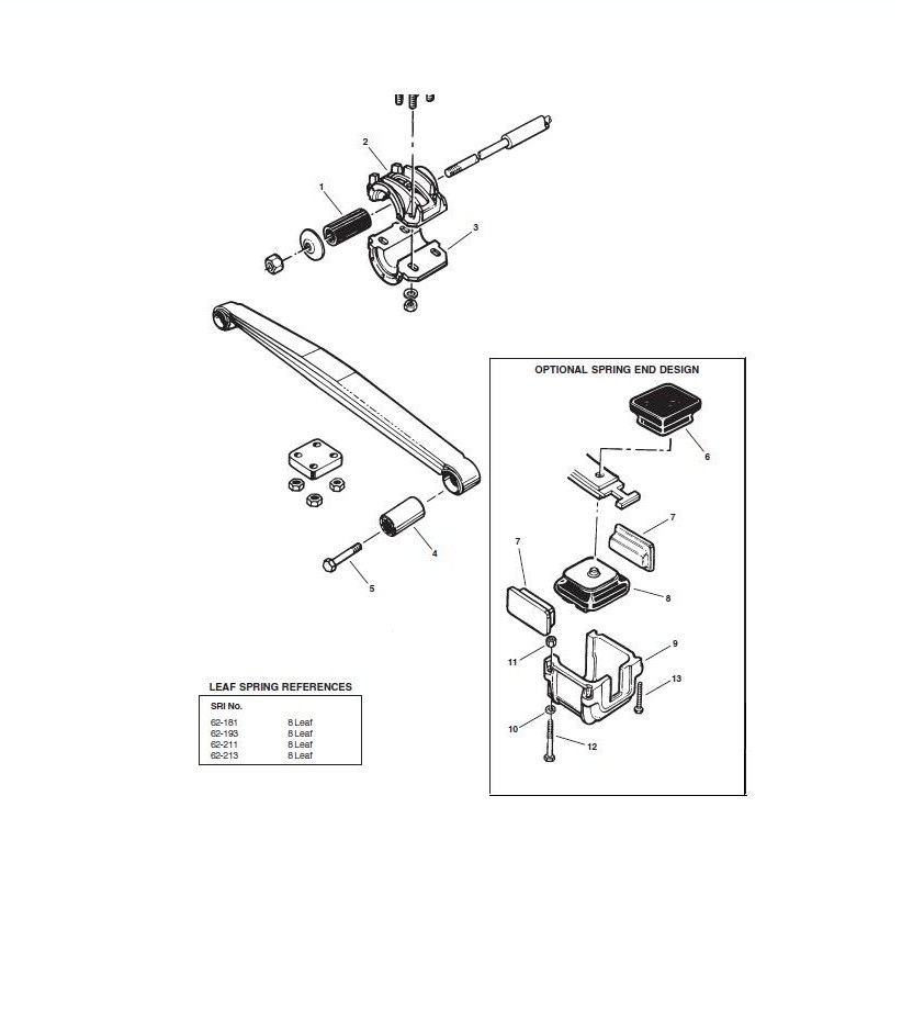
Here is some artwork of the ST suspension from the Euclid Parts Manual

-
Are you are referring to the Mack ST suspension? This suspension was set up similar to the camelback suspension. It had a trunnion & bushing, etc. like the camelback or SS suspension, but was only 3 or 4 leafs. The springs were attached to the axles at one time with buckets & cushions like on the SS, but later with eccentric eye bushings that allowed for axle alignment. These tended to be a problem if not maintained. At on time Mack issued a recall on the suspensions axle attaching bolts.
-
 Yes I've seen this happen with ABS sensors too. In our case the tip of the sensor was rubbed through causing the seonsor to short intermittantly when the teeth on the tone wheel passed it. Always reset the sensors when you have the opportunity (sometimes they freeze up in the mounting brackets and can be a real pain). Just push the sensor all the way against the tone wheel on the hub and it should be ok (this helps to keeps them from freezing up in the mounting bracket). The sensors will self adjust from there. Remember to clean the tip of the sensor and the tone wheel as well.
 -
Sometimes this doesn't work due to damage in the guage panel circuit. Most of the time all the other features work but the buttons are damaged. Even though they feel like they are ok they sometimes don't work for guage/bulb test or fault reading.
-
It's the fuel Injection control (Bosch) module.
-
Check the fuel system check valve on the right rear side of the engine above the air compressor
-
Sorry for any confusion. The wiring shown in the Jake installation manual is for a truck that was not built with the Jake harness integrated. I don't happen to have a wiring diagram for your year model handy, I do have one for a CH 1993-1994 with factory wiring for Jakes which should be set up about the same as on the RD with the biggest difference being wire numbers (which you probably can't read anyway due to fading). They may or may not be the same, I'm not sure. I have removed the extra wiring shown on the diagram so all you see is the engine brake wiring. The wire numbered 22-A-.8 is the first wire in teh circuit, it goes from the fuse to the jake switch and the relays. When the jake switch is turned on low power goes to pin 85 on the low relay, it goes to pin 85 on both relays in high position. Power goes through the relay and exits on pin 86 and goes to the clutch switch, form the clutch switch to the fuel pump switch, from the pump switch to ground. when this happens the relays (either the low if in low position or both if in high position) switch internally from pin 87a to pin 87 allowing power to flow from pin 30 through the relay and out to the jake solenoids. Some or all of this circuit may still be intact on your truck, you might want to check the jake housings on the left side to see if there are any wires connected to them and so on. Factory Jake Wiring.pdf
-
I think those should be your wires, but its been a while since I've looked at one. If I remember correctly there are two wires in separate weatherpack connectors on the right side of the cab bulkhead about halfway down the branch harness for the hood. You will need a jumper harness to connect from the cab wires to the pump. Check to see if the wires have voltage when conditions for brake operation are met (per the installation manual linked earlier), then see if voltage is gone when the clutch switch is open.
-
Don't forget to install the oil supply tube in the auxillary shaft (the shaft that drives the compressor). It supplies oil to the air compressor. It's a small piece of steel tubing about 1/2" diameter and about an inch long. It just slips into the back of the auxillary shaft or teh front of the aair compressor crankshaft.
-
Here is a link to the Jacobs Vehicle Systems installation guide for your engine brake. http://www.jakebrake.com/service/pdf2/018061C.pdf Page 10-13 shows the wiring system for the engine brake (both mechanical & VMAC). Your truck probably had the wiring there already, but this should give you an idea of what the circuit looks like. Since you found a switch on the pump you should be looking at the non-VMAC wiring. I can't remember the color of the factory installed wires coming from the cab to the pump switch, but I think they're brown. Hope this helps.
-
MMost likely from the injector cups (that the injectors sit in). They are sealed with an o-ring at the top of the cup & swaged into the head at the bottom. The cups have been something of a weak spot. I would suggest having a dealership check it out. It is an in depth repair requiring special tools and may still covered by your warranty.
-
Wastegate Turbochargers — Description, Operation and Troubleshooting SB 214-017 According to VMAC III Service Manual (publication # 8-211) there is a 3300 ohm resistor in the wastegate actuator circuit. An out of whack reading in the signal line will set code 4-5. Since you don't have a fault lamp this probably isn't the problem.
BMT Forum Logo
