


T-Mack1
-
Posts
123 -
Joined
-
Last visited
-
Days Won
1
About T-Mack1

T-Mack1's Achievements
")


-
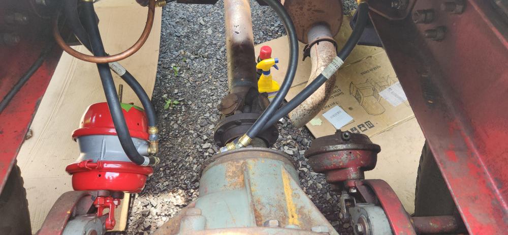
Attached picture is when we converted to Spring brakes. Left side is new dual chamber spring brakes, right side has the single chamber "service only" chamber. Conversion requires a quick release valve (QRV) and a park brake valve (& knob on dash), plus plumbing work. We used plastic pipe (synflex). Next, the way the forum is setup, you only get so many bytes of upload for free. I spend the $75 to get unlimited upload. Makes showing/helping others easier. It also helps if you are asking for help and want to show a picture.
-
Nice find. Your compressor unloader (also called a governor) looks like the one that is on our '57. It's the thing on the right side of first picture (horizontal cylinder). We don't have an air dryer (wet tank only), so ours only has 2 lines. Bigger line from air tanks, and 1/4" line down to compressor to "unload"/turn off it off when pressure is reached. If you need a picture, let me know. I'm not sure what the other two things are in the picture. We have a low pressure alarm switch in that area but it looks different. Next, I see you have a drive-line parking brake (brake lever in cab). Do you have "service only" on the rear or did someone convert it to Spring brakes? Ours was service only but we converted to spring brakes.
-
 Yep, Mack made boat engines. And stuff for railroads, but that was mostly small tugs.
 -
Mack AC Cylinder Removal
T-Mack1 replied to Great White's topic in Antique and Classic Mack Trucks General Discussion
Glad to hear you got them off. The sweet feeling of success is a great thing!!!!! -
Mack AC Cylinder Removal
T-Mack1 replied to Great White's topic in Antique and Classic Mack Trucks General Discussion
Have you tried to apply heat to the engine block to expand the metal? And, heat cycling where you use a penetrating oil to cool it back down may help. DO NOT hammer on it. The metal could be brittle with age. -
Online auction is active. https://tomhallauctions.hibid.com/catalog/706752/01-20-2026-mack-truck--primitives--beer-items--plus-
-
Like said above, driving it down the road verse trailering changes stuff. And ours, a firetruck (from a major city to boot) adds to the decisions. Safety becomes an issue if driving down the road. We changed our "Service Only" brake chambers on our '57 B85F to have spring brake chambers on the rear. We are planning to drive the grand kids around and that was a no brainer. Yes, very visible and had to add the yellow knob on the dash. The QRV is hidden under the firetruck "turntable" ( the equivalent of a fifth wheel but is for a permanent mount fire trailer (Hook & Ladder)). The firetruck dual starter buttons , the two separate battery systems and the run the ignition off "Battery A or B" switch is a discussion Jack and I have repeatedly. I'm leaning towards keeping it, but battery technology today verse 1957 makes it almost not needed, especially on a truck that's no longer on emergency response duty. So, keep it because it's sort of neat, or get rid of it (or not use the buttons but leave them in place) because it's not needed....?? Paint..... On a working truck, unless it has Historical value (like a UPS truck, or the Bethlehem Steel truck at the Museum), it's a new owner choice. That includes doing one of those patina looks. On ours, as a firetruck, a previous owner (Mr. Barton from East Hampton, CT) repainted the truck and put his own lettering on it. "Barton" on the hood, and "Ladder 1" over "East Hampton" on the doors. It originally had "Boston" "Fire Department" on the hood, and "Ladder 11" on the doors. After a bunch of talking, where I really wanted it back to the Boston Scheme, verse a "Mack Family" scheme, I think we are headed to the Boston scheme. More Historic, and a conversation starter. There is a thought to have a list of owners somewhere but that is far from important at this time. Trolley valve...... the trailer is long gone, so it does nothing (lines are plugged). Jack is leaning on getting rid it. My plan is to convert it to a type of manual Hill-Start (Mack "Grade Gripper"). Our treadle is a single circuit type, so easier to work on. I picked up a double check valve at the Mack Museum garage sale this past October. It has 2 inputs, 1 output. where one input shuts off the other. This will prevent the Trolley valve from venting thru the not pressed brake treadle and venting air and, vice-a-verse, when using the brake pedal, air venting out the trolley valve vent. That's going to be a hidden upgrade, so not many people would understand it's there. Note, I also picked up a modern 2 circuit treadle and a governor (compressor un-loader) at the garage sale, both NOS. Converting to Primary and Secondary air....... talk about a lot of work. Good work, but very tedious. Then there's the wiring. Restore to original functions or make it more modern. It's mostly hidden so only some people will notice. For ours, Doug Maney, the curator of the Mack Historical Museum, said to me "Tom, you will find that firefighters think they are electricians, but they are not". Need I say more. In the rewiring, I keep wanting to make it more modern (the electronic tech in me) , using more relays to shut things off when the key is turned off (yes, adding a key is another upgrade for a firetruck). Jack, the Master Electrician, wants to keep it simple and that means more original. Wheels, Update or keep original. That's more on how much you want to spend. Shiny Aluminum, modern size rims, etc etc. We have 11.00-20 tires on the 3 piece Budd rims (sliding ring (bead ring) that hold the split lock ring in place). The price of 20 inch truck tires is rather high now a days, because they are now custom ordered at most places. So we are converting to 22.5 inch Budd rims. Wanted the "Five opening" rims, but they are hard to find. Picked up 6 Accuride "Two opening" rims at a great price. But now I have a lead on 4 "five opening" ones, and if we get them, 4 of the two opening rims will be available. We now got tires for the rims. Just a matter of sanding and painting the rims. Dream: add a second row of seating for the grandkids. That will be a very noticeable modification. But, depending if a lead on another "open cab" cab pans out , it could look awesome and raise the value. And I would like to make it a bolt on addition, so it could go back to a Tractor-Drawn-Aerial-Ladder if someone "gives" us a tiller trailer and a free space to store it. So........ the decision seems to be a Concourse Trailer Queen or a Driver. We're going for the "driver" restoration.
-
Not sure, but looks like on-line auction starts at 7PM EST on 1-20-2026 https://tomhallauctions.com/auction/griswold-neer-werk-pol/
-
I looked at the Auction House's website and a date & location hasn't been posted yet. https://tomhallauctions.com/
-
Not sure, but if they both don't work at the same time, I would think it might be a dash power supply or ground issue. Ignition switch or fuse could also be suspect....
-
Sweet!!!! one day my brother and I will have our '57 B85F to the point it could be used in parades.
-
B model fire truck. With hallscott. Engine
T-Mack1 replied to mackdump600@yahoo.com's topic in Fire Apparatus
I'm one of your subscribers. Everyone, see "Edward-Thaine" on YouTube. -
B model fire truck. With hallscott. Engine
T-Mack1 replied to mackdump600@yahoo.com's topic in Fire Apparatus
Morris Me, Are you the father & son Youtuber's that have a two B model fire trucks, where at least one of which is a B21? -
Some tv show/or YouTube video I watched a few months ago had a hydraulic pump for the steering that somehow was mounted to the back end of the generator. I always wondered if one of those new electric assist units they make for custom cars could be fitted.
-
I guess I was spoiled. Up until January '25, I worked at the Mack factory. If a truck bleed down over night it was looked at with a fine tooth comb. Actually an electronic air leak down tester, and sometimes a sniffer which is actually a extremely directional microphone and a headset. I forget the spec, but 0.3 psig in five minutes sounds familiar as the limit. And that would be with air brakes applied (bracket thing holding pedal down). Many pass with no leaks at the test. Note: a 0.3psig leak would take approx 36 hours to go from 130 psi (average compressor cutoff on new trucks) to zero psig. Although the PPV (pressure protection valve) shuts off the accessories at 90psig, so it may take longer.


BMT Forum Logo
