


oldspwr
-
Posts
151 -
Joined
-
Last visited
-
Days Won
7
Content Type
Profiles
Forums
Gallery
Events
Blogs
BMT Wiki
Collections
Store
Posts posted by oldspwr
-
-
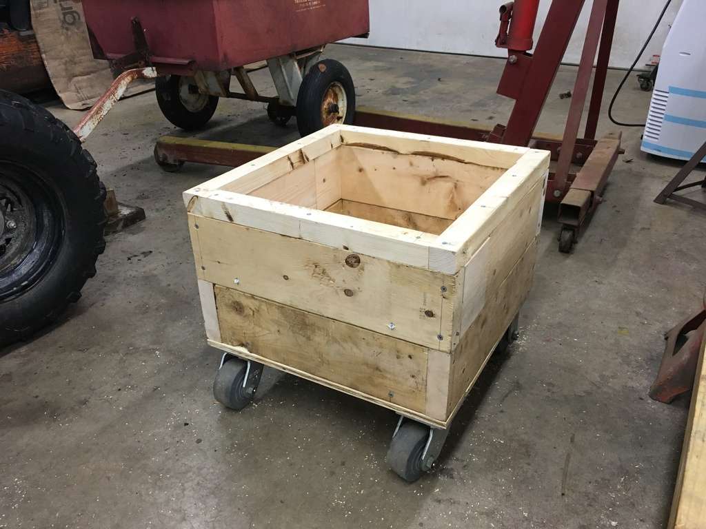
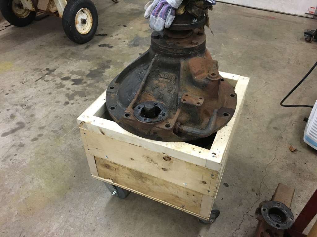
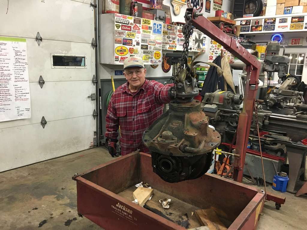
Then using some 2x6’s and some extra heavy duty casters I had, I made a quick ‘box’ to be able to move the pumpkin around. Besides, I would need something to move or store the 6.71’s when I removed them...
Then with some ‘help’ from Maddie I was able to roll the pumpkin outside...
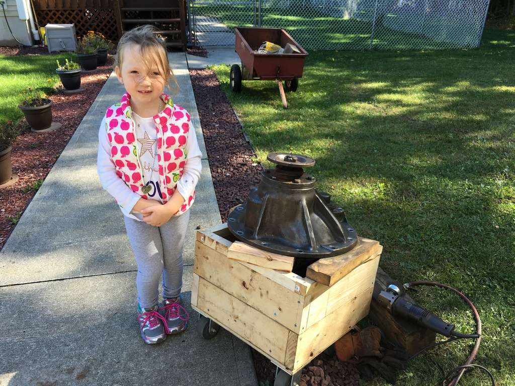
And get everything cleaned up...
More to follow...
-
One of the first things I need to do was change the gears in the truck Almost since I bought the truck, my Dad and I had always talked about finding a taller set of gears to see if it would help the truck move along a little better. Right now the truck has 6.71/9.13’s and based on several 155W specs sheets I have collected, 5.43/7.39’s and 6.14/8.36’s were also available. So I put a quick spreadsheet together a numbers of years ago to compare the ratios and 5.43’s would lower my RPM’s from about 2150 to 1800 at 55 mph.
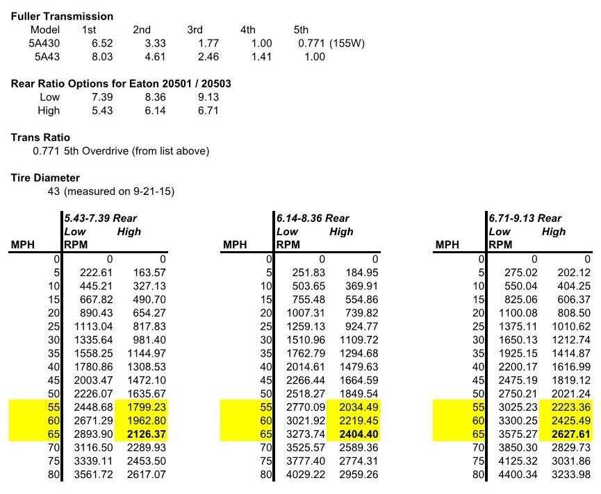
When I started looking for gears a while back, I hit a number of roadblocks since I didn’t have enough information. To make matters worse, the specs list the rears as both 20501 and 20503 and I was not able to find these numbers anywhere in any of Eaton’s older literature. A few guys asked for the casting number (28656) and I was able to find a set in Toledo OH but they wanted $1500... ouch... Then about 3 years ago I found a rear out of a 257 that came with a 180 Cummins. The casting number matched my rear (28656) so I bought the rear and set if off to the side. On a side note, I do have a spec sheet for the H257T and it only list the only available rear ratio as 5.43/7.39 but they call the rear an R454.
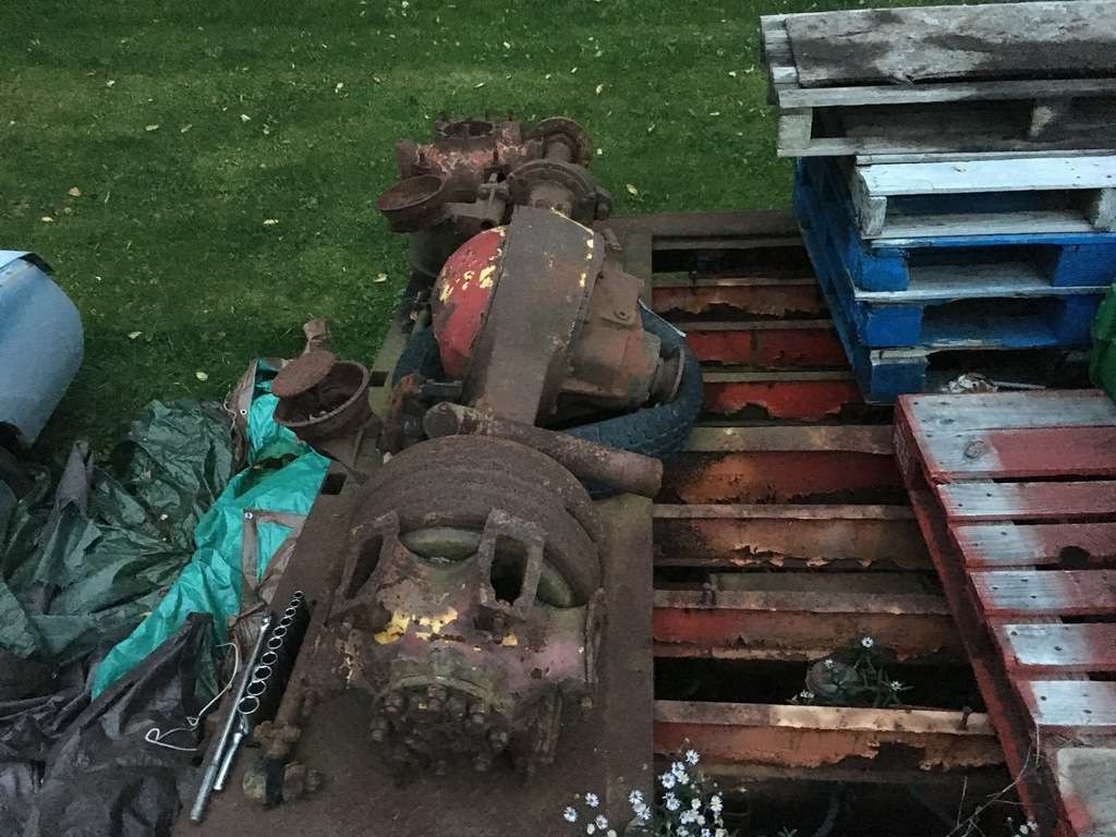
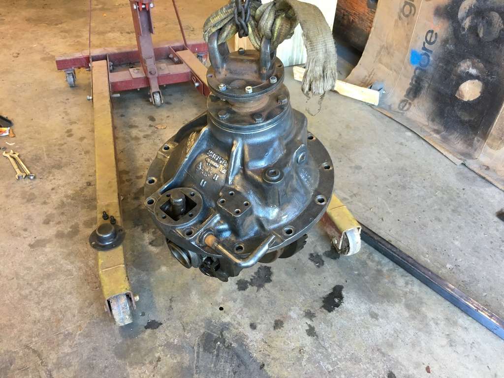
When I decided on the Cummins upgrade a few months ago, I figured I would change the gears first just to see how they worked with the Continental. If I remember correctly, I talked to the owner of the Green Apple Express 257 a few years ago and he said he replaced his gears with 5.43’s and it made a world of difference driving the truck with the 572 Continental. So I decided to pull the pumpkin from the rear and get it ready to install in the truck. But that was easier said than done... I had the rear sitting on a drop deck trailer on the far side of yard and at the time I wasn’t able to bring the trailer over to the garage to lift the pumpkin out with the fork lift.
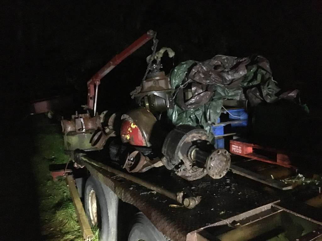
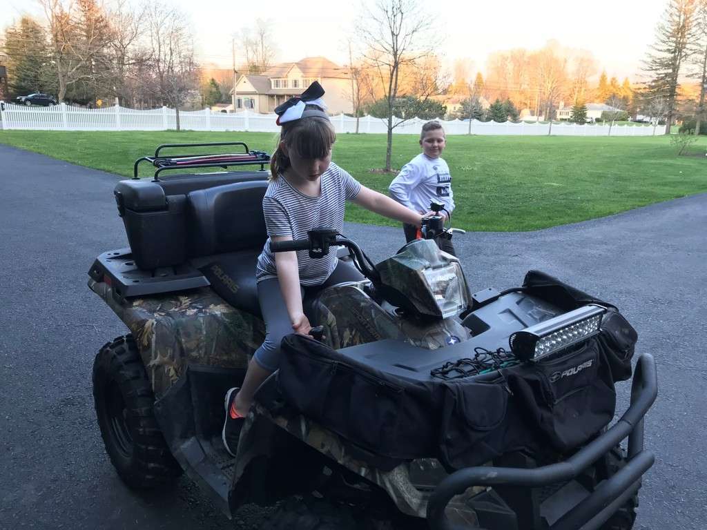
So we wound up using the cherry picker and my 4 wheeler along with a utility cart, in the rain I might add, to get the pumpkin in the garage...
More to follow...
-
- Popular Post
- Popular Post
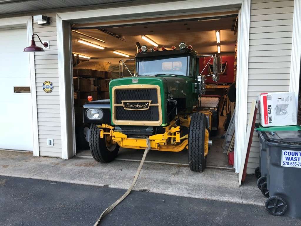
Unfortunately when the Brockway site crashed a few years ago I lost my original build thread for my 55 155W Brockway. This truck was originally ordered by GLF from Ithaca NY. It then went to the Town of Enfield in NY and then to a private owner. When the private owner passed away, Bill Fletcher from Trumansburg, NY bought it. In 1999 my Dad and I made a trip there to look at some fenders for a 260XW and one thing lead to another and I wound up buying the 155W.
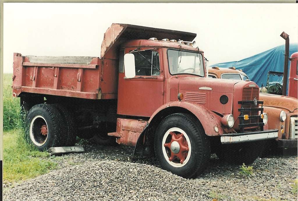
We completely restored it over a course of 7 years and finished it in 2008. By 2016 I decided to replace the Continental with a 5.9 Cummins. So this is the build thread on how I did it. I thought it would be a good idea to share it here...
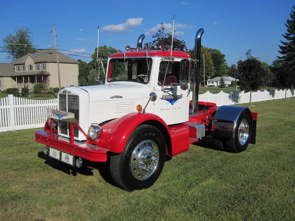
I finished the 155W in 2008 and so far I have put a little over 7300 miles on it. Even with having the 361 and 761, I really enjoy driving this truck. So I decided it was time to make a few changes...
The 42BD or 427 flathead Continental has been a great motor but really doesn’t have the power you need for today’s roads. It will run 55mph all day long on level road but once you hit any kind of grade your down to 40 in the right hand lane with the 4 ways on. I would like to be able to run 60 mph up a hill so I decided it would be a good time to upgrade the Continental. I did consider making some upgrades to the 427, like adding dual carbs with the Ellis manifold, maybe an MSD ignition, a Mallory distributor, etc., but most of these upgrades would have little gains verses the costs. It’s also start to leak some oil so that was another deciding factor...
So after much thought I decided to replace the Continental with a 5.9 Cummins. They are comparable in size as well as weight. I did consider the 8.3 Cummins but that weighs in at 1800lbs which is about a 1000lbs heavier than the Continental. You can also build decent power fairly economically with these motors. I also knew that these were used in some smaller Freightliners with air brakes so that was a plus since (air compressor, etc...)
More to follow...
-
 3
3
-
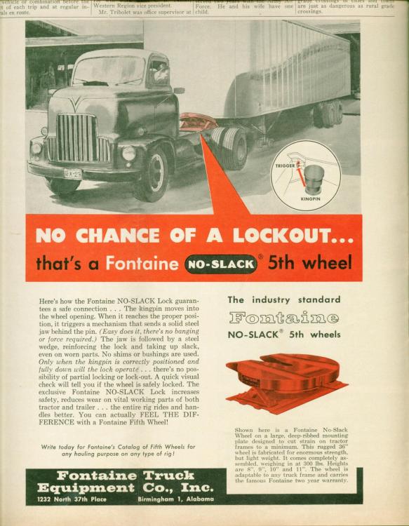
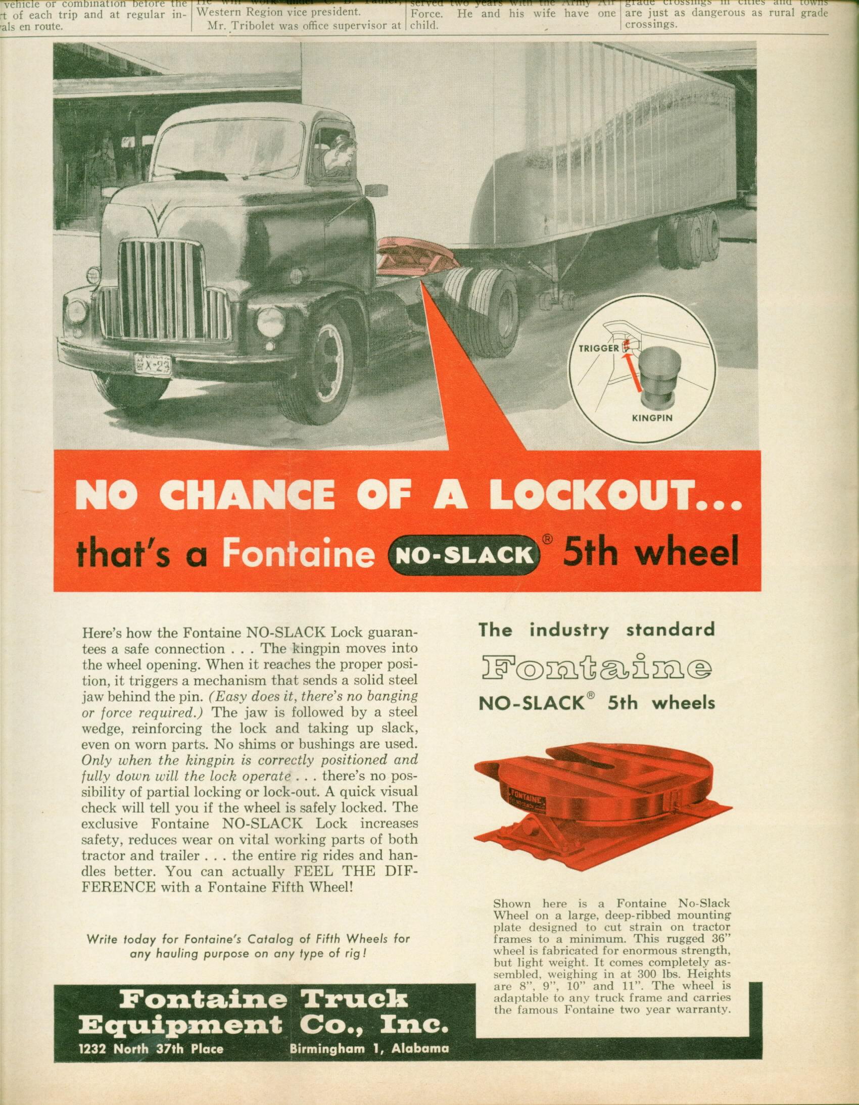
I have a Fontaine No Slack 5th Wheel on my 55 Brockway. It was given to me by a friend of mine who ran a garage for 50+years. Here is an advertisement I have...
-
1
-
-
On 10/13/2021 at 3:10 PM, mrsmackpaul said:
How soon to the end of Brockway using their own cab was this truck, I know little about Brockways so have no idea of dates at all
Paul
I will follow up a little later on Brockway cabs, etc...
-
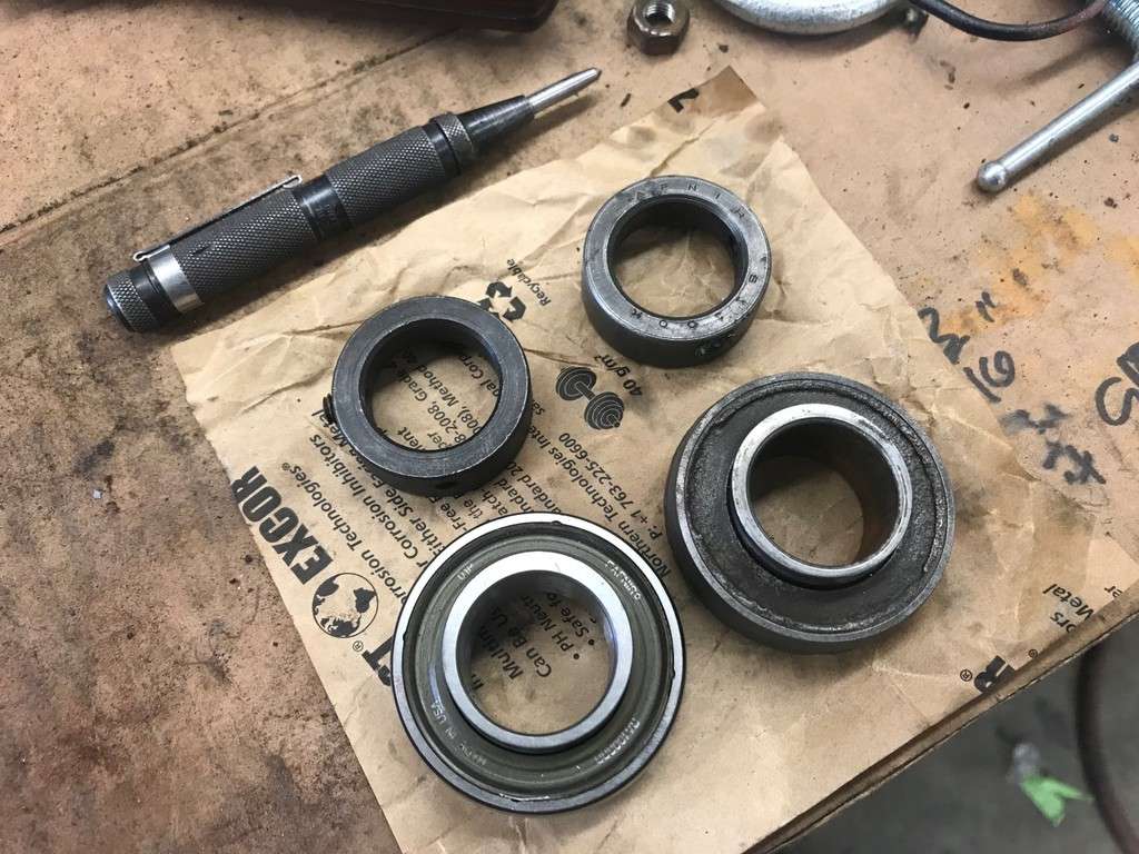
The lock ring just holds the inner race of the bearing in place. There is a set screw that tightens up against the shaft.
-
- Popular Post
- Popular Post
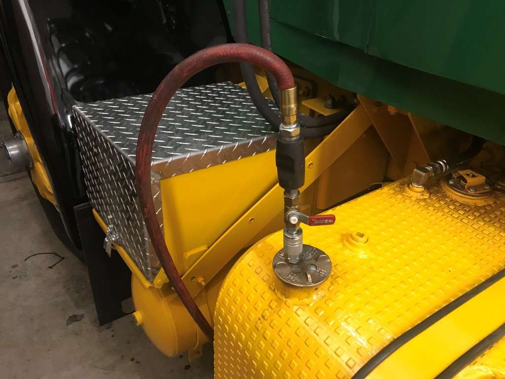
Then I cracked the valve, just enough to apply a few PSI if air pressure to the tank. Once the fuel started running out of the top of the PT pump, I shut the air off and reinstalled the pipe plug. The truck then started right up with no issues! Once I was confident my air bound issue was solved, I took the truck for another few test rides and realized I had another problem. At idle or just off idle the truck was very difficult to steer, as if the steering was bound or the power steering wasn’t working. At first I thought 500 rpm was too low of idle setting so I made a tool to adjust the idle with a brass fitting and an old screwdriver. In the meantime a friend of mine also have me the screwdriver tool he made years ago...
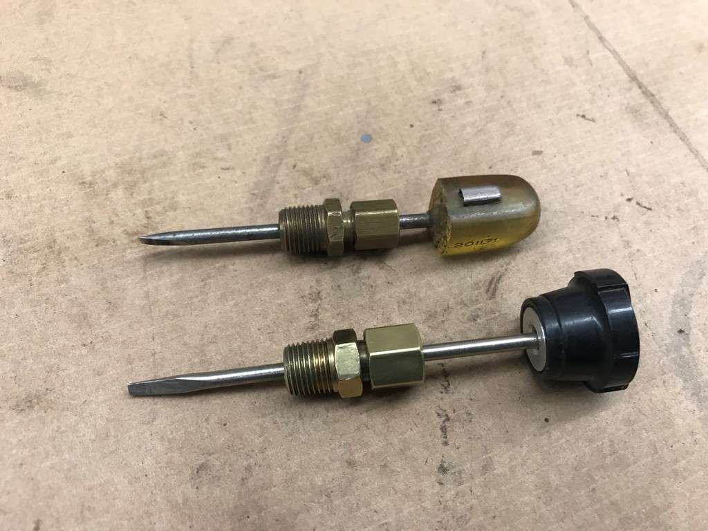
I turned the idle up to 650 and it didn’t help at all. After talking to Stan A was well as the guys on the JustOldTrucks message board (especially Tony B.), I realized my issue may be the power steering pump.
If you remember correctly I had bought a pump off of eBay to replace the original one I had. The only difference between the 2 was that the new one was rated at 1250psi and the original one was rated at 1500psi. At that time all I thought I had to do was replace the spring in the valve to increase the pressure from 1250 to 1500. So at that point I thought I had either a pressure or flow problem...
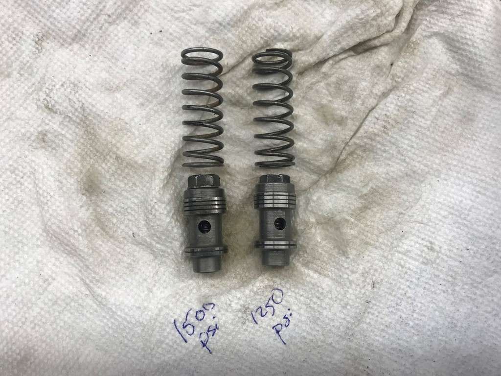
I know this part will get in the weeds a bit, but I figured I would share it here just in case it might help someone else. For reference, the correct part number for the pump was V20F 1P8P 38C 6F 11, where the 8 means in ‘1P8P’ means 8gpm at 1200rpm. That correlates to 3.33gpm at 500rpm (idle). According to Sheppard’s literature, the minimum flow for their 592 steering box is 5.7gpm. But more than likely, the flow ratings given in the Sheppard specs are for the flow control valve setting not the minimum pump output at idle.
At this point I started doing some research on what Vickers pumps were used on other Brockways. A few guys on FB went out of their way to get the numbers off of their pumps and I was able to put this list together...
V20F 1P8P 3C 6F 11 - This appears to be the correct number for a pump on an 855 Cummins.
V20F 1P9P 3C 6F 11L - This appears to be the correct number for a pump on a 671 Detroit. Left hand
So it looks like the Detroit has one more gpm at 1200 rpm (8 verses 9) and is left hand rotation.
Regardless, Joe D had a parts 671 Detroit motor and let me borrow the pump off of it.
I removed the valve and spring from this pump and cleaned it up. At that point it dawned on me that when I swapped the valve over from the pump I bought on eBay, I used the wrong valve body. The valve body and the orifice are slightly different. In fact the 1500psi valve has ‘15’ penciled on it with a scribe. So in reality I only had 1250psi of pressure when I needed 1500psi...
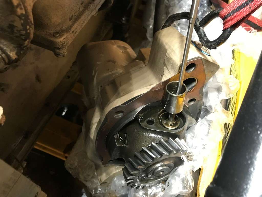
I was able to remove the pump from the back of the oil pump without disconnecting the lines. I was also able to remove and replace the flow control valve and spring without losing too much oil. A half hour later I was able to drive the truck out of the garage, and easily turn the steering wheel with only one hand!!!The following weekend Russ called and asked if he could stop by and visit. Once I hung up the phone I pulled the truck out of the garage and warmed it up. Right after Russ showed up we went for short ride around Daleville...

I did take the truck to our Harford show and put a few miles on it driving it locally. Tommy and I also took it for a nice ride, right before the snow we got last week...
And that wraps things up for now!!!
-
2
-
 1
1
-
Thanks for everyones comments, I appreciate them!!!
When we last left off I resolved the oil pressure issue I had. One of the things I noticed with this truck was that it was very difficult to drive smoothly. In other words when leaving from a dead stop, it seemed as if you either gave it too much throttle or not enough, and when you had it moving it was surging. I met Dave Crump at Macungie and he explained that my problem was common to the earlier Cummins PT pumps.
This was the pump that was originally on the engine...
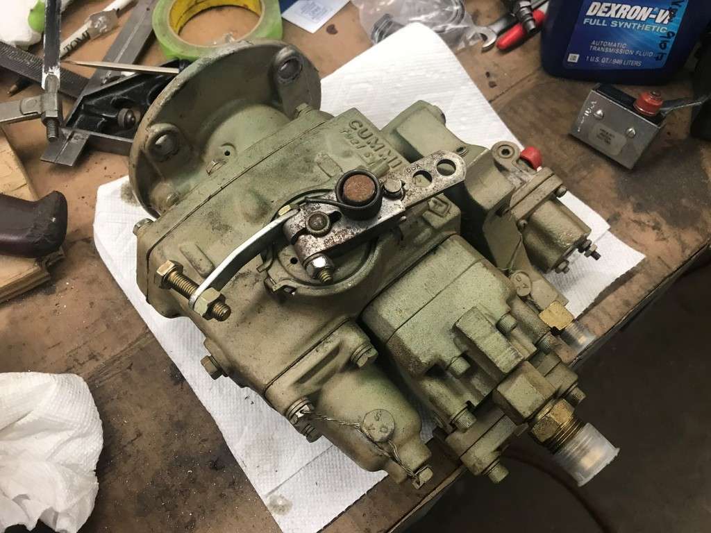
After a few more discussions I sent him my PT pump and he wound up sending me back a later AFC style pump. He set it up for an NH280 which was the highest horsepower non piston cooled Cummins (I believe...) And this is the later style pump he sent me...
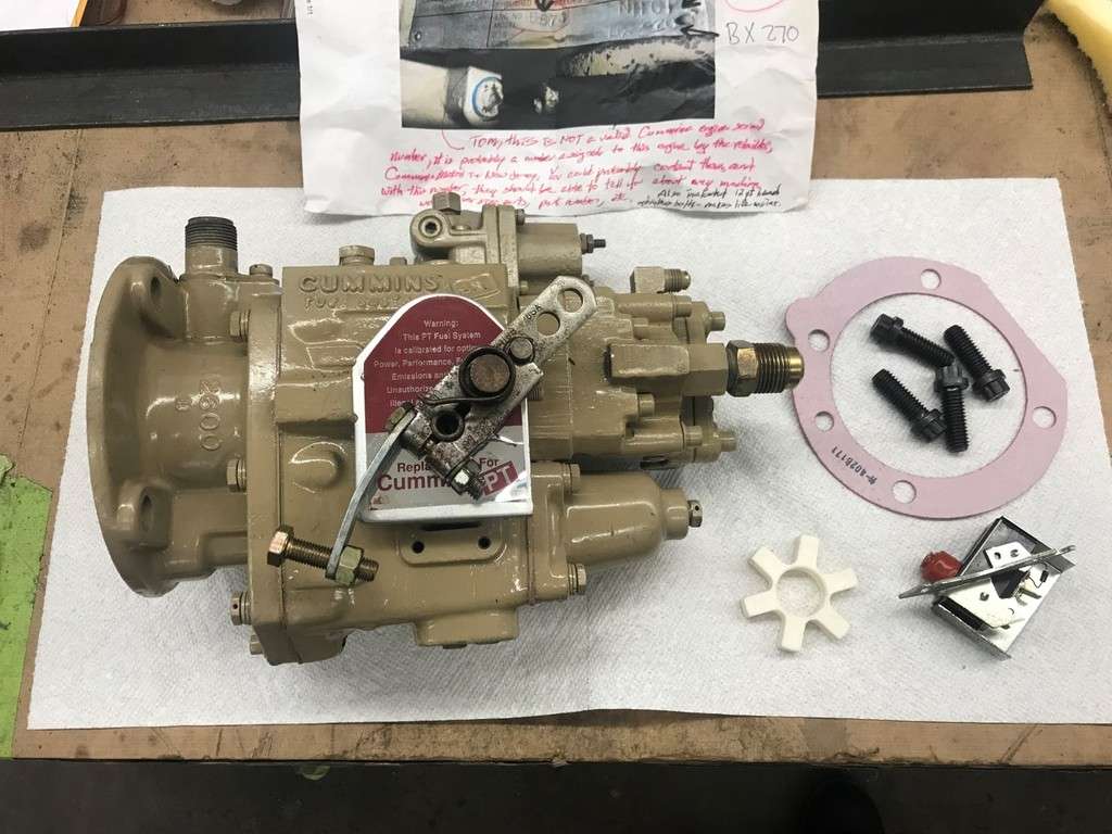
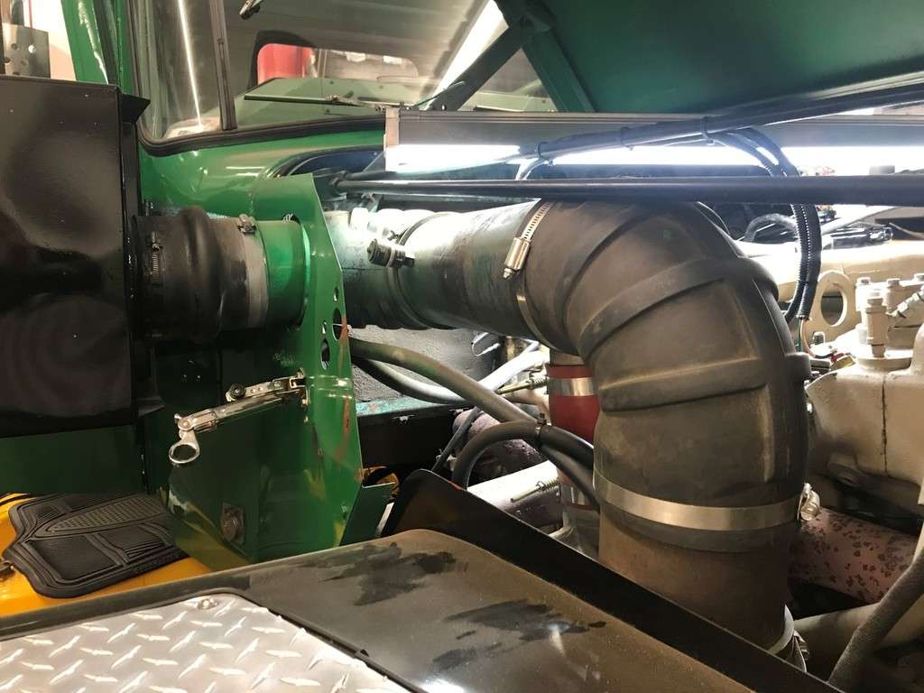
To install the newer pump I had to pipe in an additional fuel return line and use a short extension to feed the fuel line that runs to the rear of the block. I also had to relocate the air intake that went from the air intake manifold to the air compressor since it now interfered with the tach drive cable. While waiting to get the pump back I also replaced all the fuel lines with new push to lock lines...
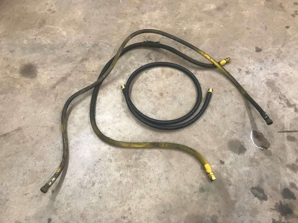
And I also drained the fuel tanks and cleaned the fittings and valves...
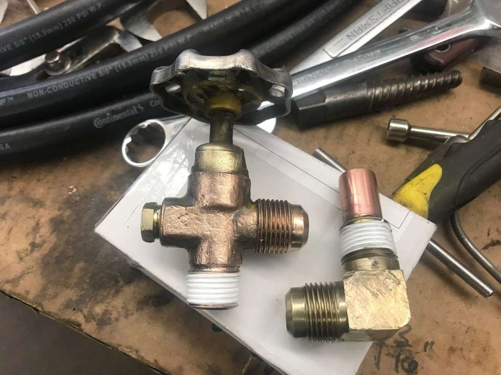
Once all of the lines were on as well as the new pump, I filled and reinstalled a new fuel filter and topped off the injection pump. I really struggled with getting the truck to run and had no throttle response as well. Turns out I still had a ton of air in the system. To help bleed all the air out, I took an old fuel cap that had a busted lead plug in it, drilled and tapped if to 1/4" NPT and installed an air compressor fitting.
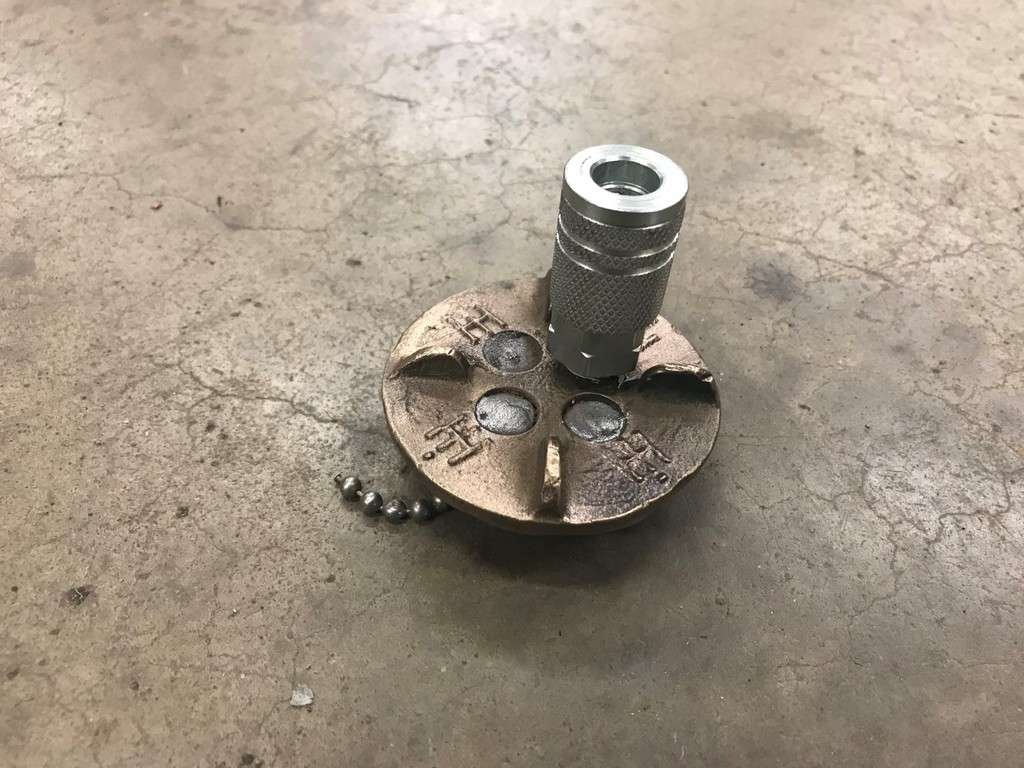
I then removed the pipe plug from the top of the PT pump and used a valve I put together to air the trucks up...
More to follow...
-
- Popular Post
- Popular Post
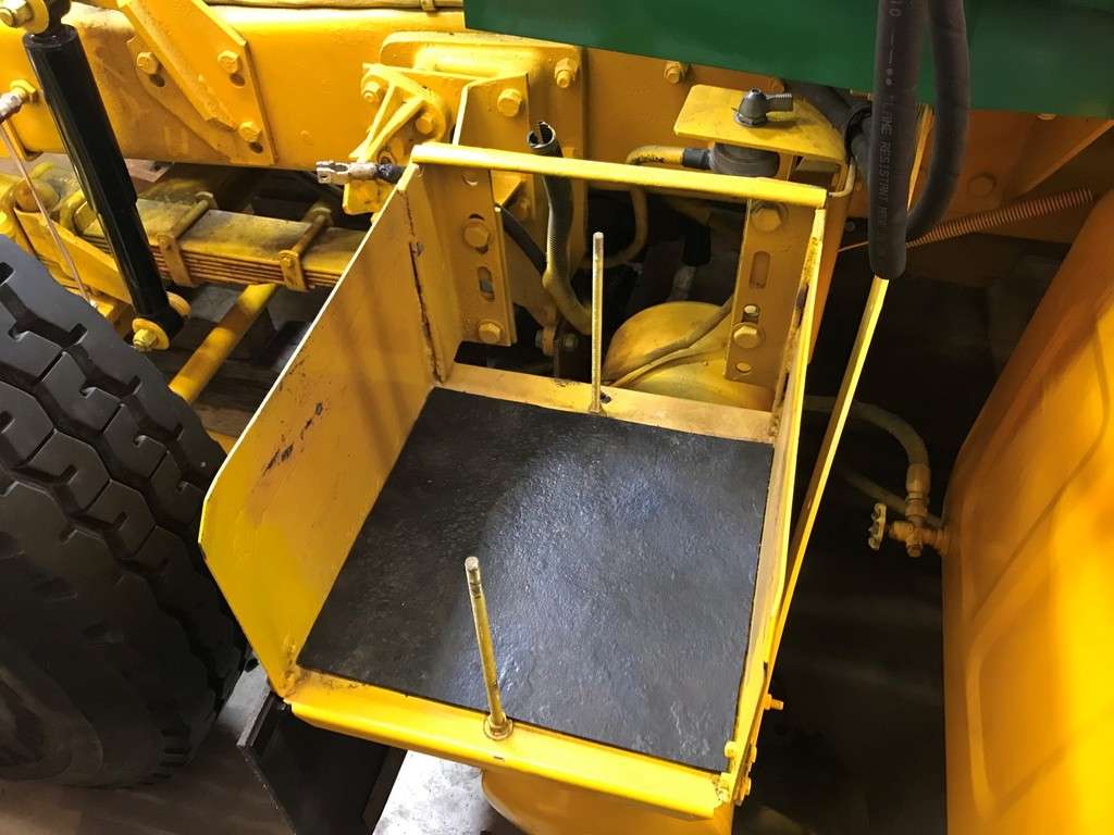
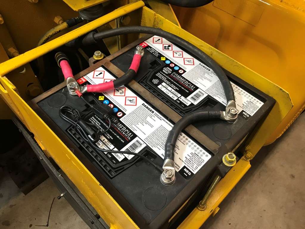
Once I was done with the steering shaft I moved on to the batteries. Russ had (4) 6V batteries in the truck, (2) in series for 12V and then those (2) in parallel. The pass side batteries were still good but the driver’s side wouldn’t hold a charge. They were probably pretty tired so I decided to replace them with (2) 12V batteries in parallel. When I removed the old batteries I cut a piece of mudflap to line the bottom of the battery box...
I also upgraded to 3/8” stud terminal batteries instead of the regular battery terminals. This way the 360, 361 and 761 would all be the same. This truck already had good 2/0 cables so I picked up some new 3/8” hole ends at Napa and a pair of new batteries. I also added a permanent pigtail to connect a Battery Tender...
After all was said and done I was finally able to start the truck. Instead of trying to start it in the garage, I had the kids pull me out of the garage with the winch on the 4 wheeler. Maddie ran the winch and Tommy watched both sides. I really had it shoe horned in the garage over the winer...
The truck was finally seeing daylight after an extended stay in the garage!
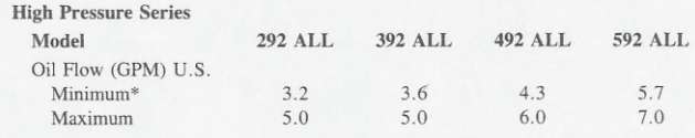
Once it was outside the truck started fairly easy after sitting all this time. But I quickly realized that something was up with the oil pressure...
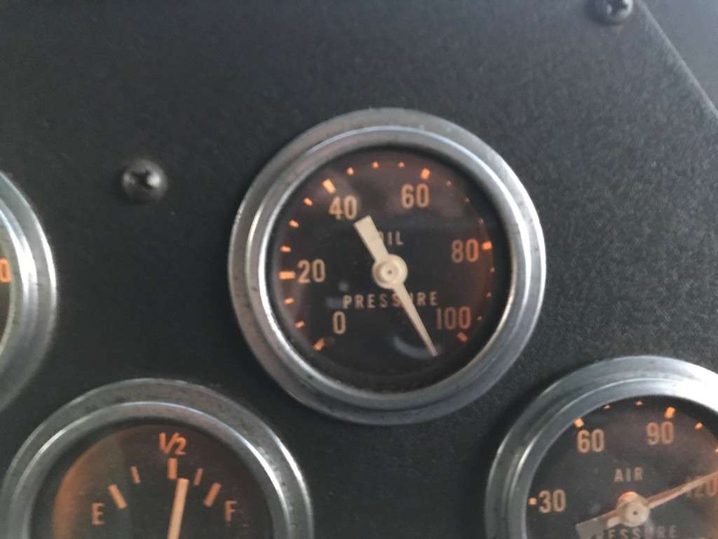
For some reason the oil pressure gauge was pegged way past 100. I put the truck back in the garage and tried to figure out what was going on. After much research and a handful of texts to Stan I realized the oil pump that I got from Dave M. was off a NH290 CPL #217. It turns out the 290 had piston coolers and the NHCT270 did not. In the later oil pump, they set the oil pressure up for 120 psi and then further reduced it in the oil cooler with another regulator/plunger/relief valve. After much thought I decided to remove the spring and valve from the original pump and compare it to the new pump. Of course this meant removing the new oil pump from the engine. This was a bit of a chore since I didn’t want to disconnect or drain the power steering lines. But I was able to slide the power steering pump back and pull the oil pump out.
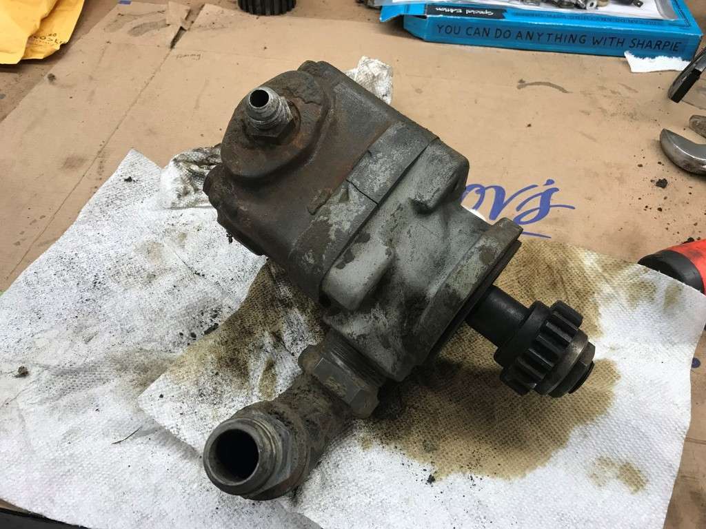
For reference, here is a comparison of the two relief valve/plungers and springs...
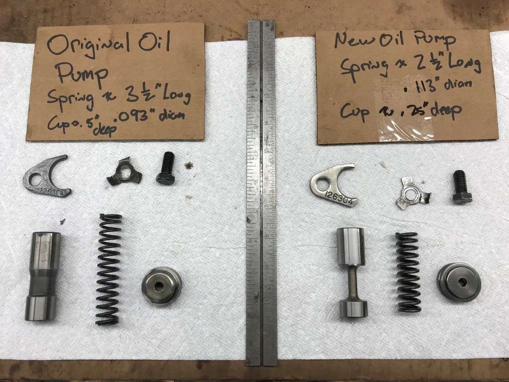
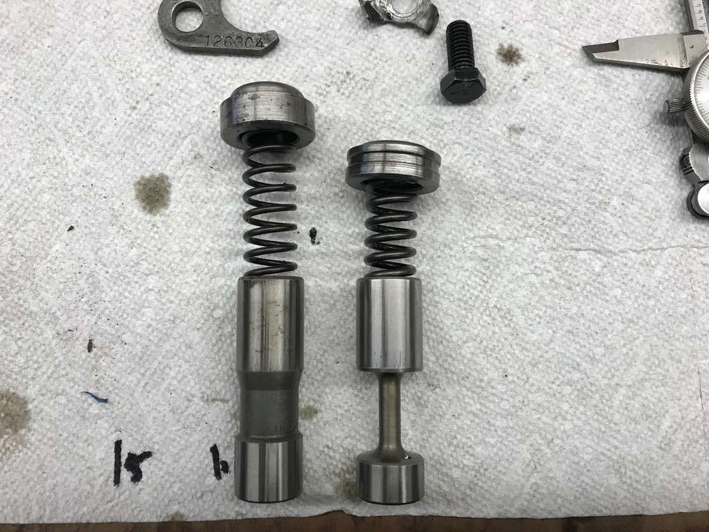
It also turns out that the original retainer cup is 1/4” deeper than the new one. So I decided to use the new plunger (since the reliefs and landings are cut differently) with the original spring and retaining cup. Although the new spring is 1” longer the coil stock is smaller in diameter so there is less pressure. At that point I reinstalled everything and started the truck back up. This time I had 78 psi at cold start up... Much better...
So the good news is that I was able to take it for a short ride around my folks neighborhood and the power steering seemed to work very well. The bad news is that it started raining so I pulled it back in the garage.
That’s it for now...
-
3
-
When I last left off I had just finished working on the air inlet piping from the air filter to the turbo. I had decided not to install the drag link or pitman arm until the truck was just about ready to be driven because without these items it allowed me to get closer to the motor. But since I was 99% done with everything I decided to install them.
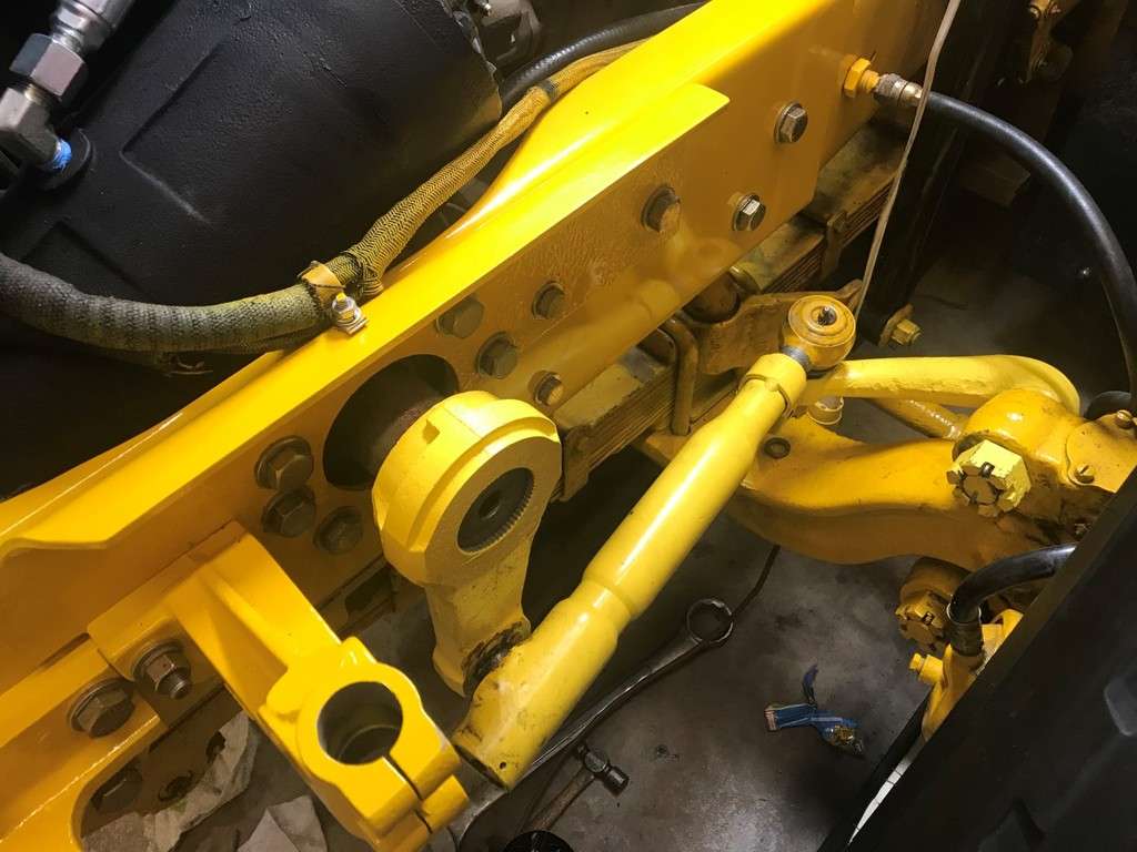
After I installed them I realized the drag link between the steering arm and the pitman are was not even close to being parallel with the frame. The pitman arm still had to get pressed on at least another 1/4" but even with that I wasn’t close. I crawled under my Dad’s 361 and that drag link was fairly parallel to the frame but it also had a ‘job’ in it. At that point I remembered that Russ had given me a 1/2" spacer with a Sheppard box.
I did have some room between the steering box and the radiator so I decided to install it. Instead of removing everything, I cut the spacer in half and then installed one half at a time. In the meantime I stopped to check out the progress on Paul Polcha’s 761 and his setup looked very similar to mine so I was comfortable with installed the pitman arm on the rest of the way...

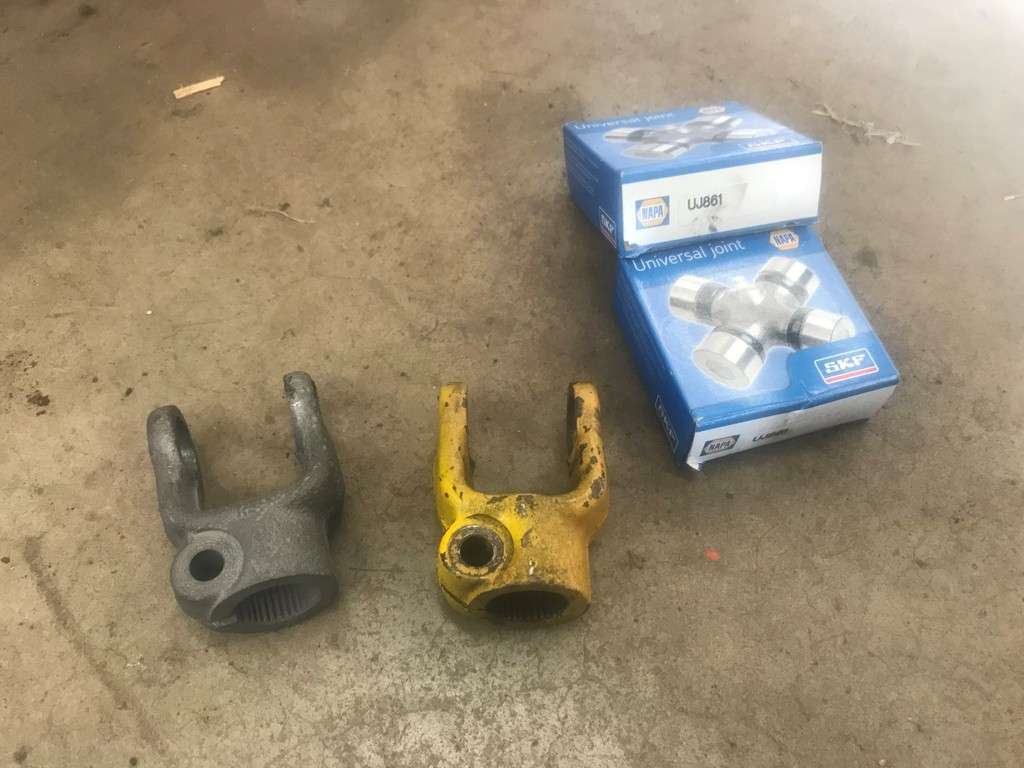
After I was done moving the steering box, connecting the drag link to the steering arm and adjusting the ball and socket spring end, I slid the steering shaft on. Once I did I realized that all the U joints were very tired and the bearing at the bottom of the fire wall was tight. For some reason I completely forgot about these. Fortunately Napa has the U joints in stock (part number UP861 or Neapco 1-1475)...
After I disassembled the shaft I realized the u joint cups were spinning in one of the joint ends (the yellow one) but I was able a better one in my collection...
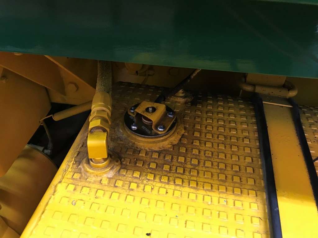
The other bearing I mentioned is located at the bottom of the firewall where the steering shaft goes through. These are the parts that hold it in place...
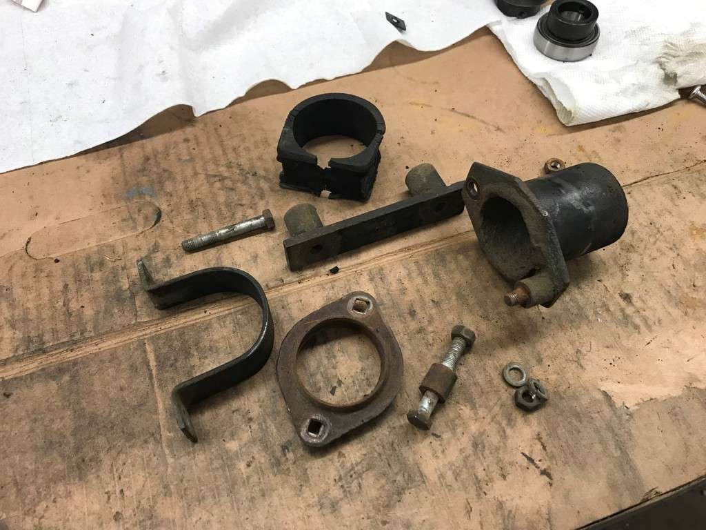
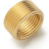
This bearing is held in place with a lock collar and set screw, just like the shafts on my snowmobiles. This bearing is a Fafnir RA100RRB and it comes with the lock collar...
I wound up sandblasting all the parts, giving them a coat of black paint and reassembled everything.
More to follow...
-
1
-
1
-
-
- Popular Post
- Popular Post
Then I started cleaning the rubber pieces. I started with Simple Green but there was some dirt on them that just didn’t want to come off. I would up having to use lacquer thinner and that did the trick...
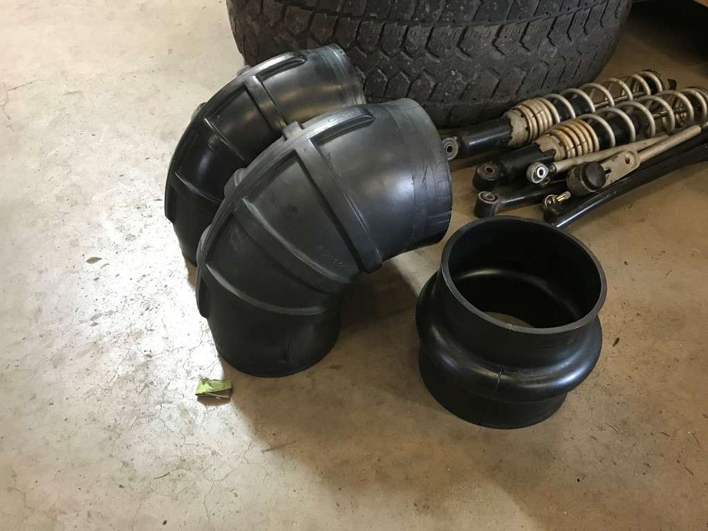
The metal pieces had seen better days also...
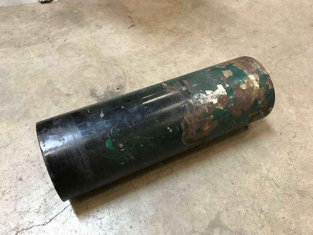
So I decided to sand blast everything, including the (3) sections of metal, the support bracket and the piece the heater hoses connect to for the heater core (more on that later...)
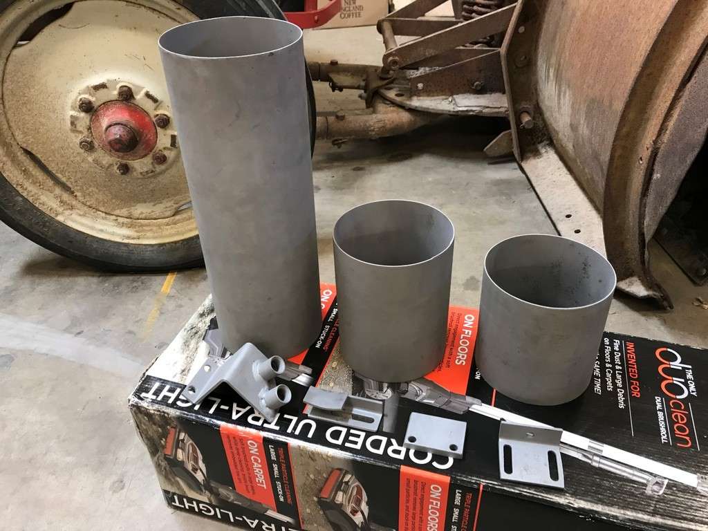
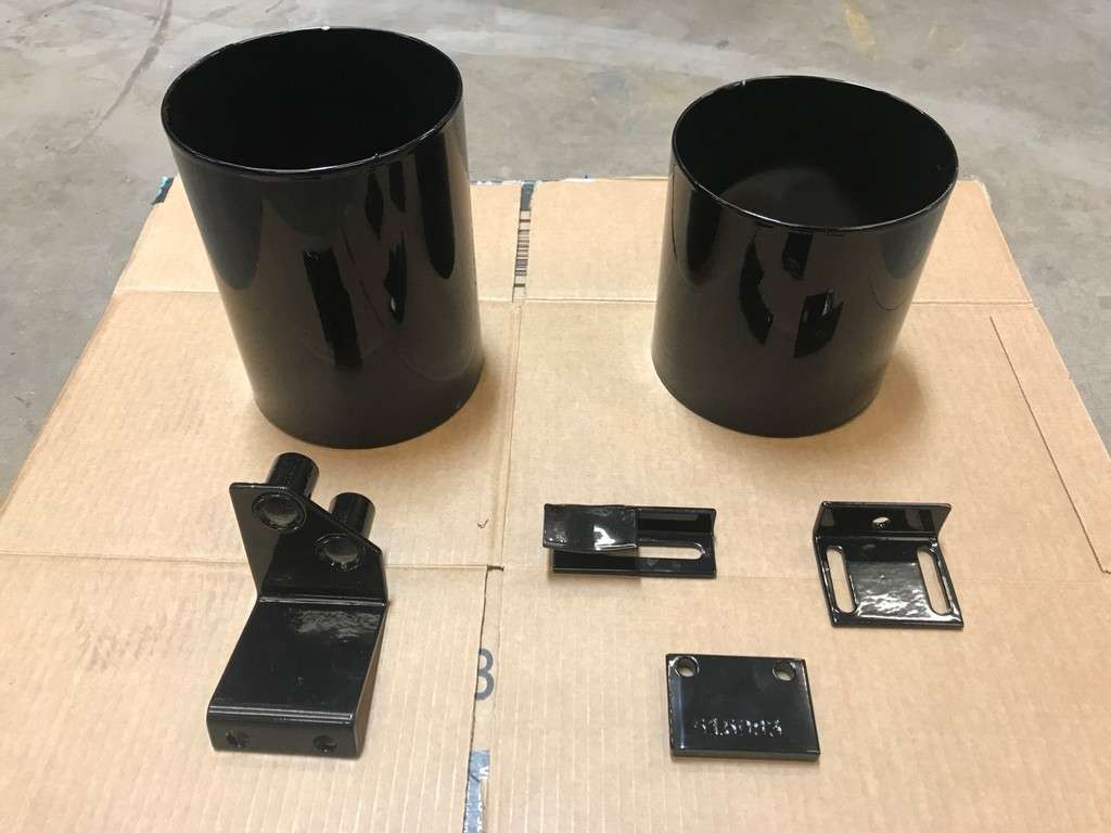
I decided to have them powder coated and a week later I got them back (except the long section, that had to be redone...)
There were a few Ideal SS clamps that were used along with some thinner mismatched clamps. I had bought a box of new Ideal SS clamps off of eBay for my Dad’s truck so I had enough left over to make them all match. These clamps used to be made in the USA but unfortunately they’re not anymore. The existing ones had some overspray on them but they clean up really will with a fine wire brush on an electric motor followed with some buffing...
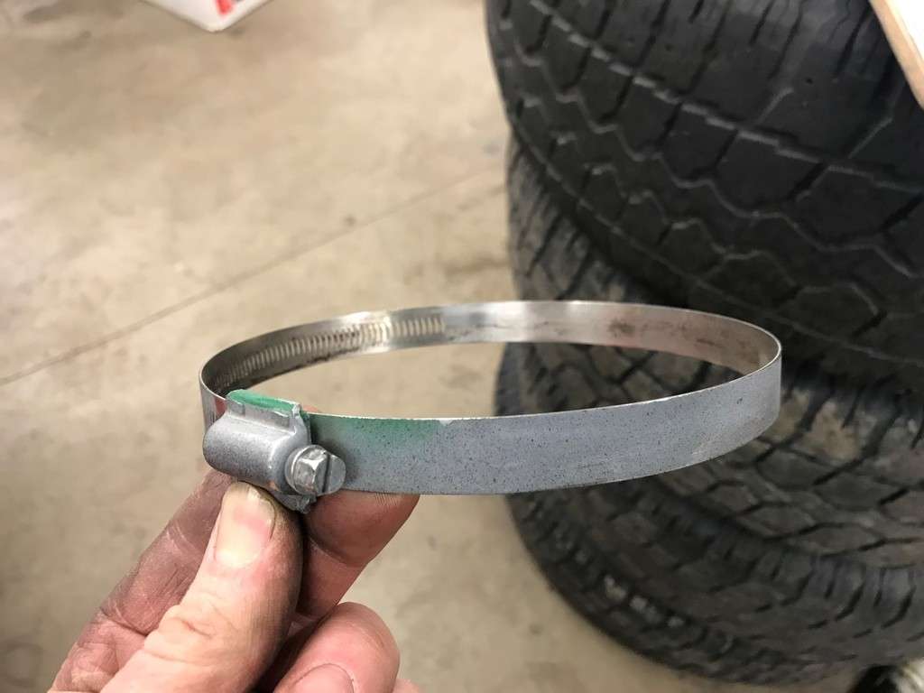
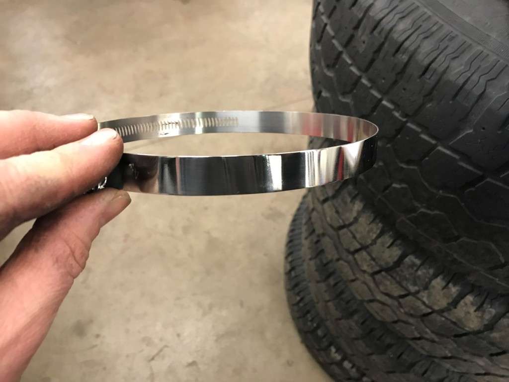
Once all the clamps were cleaned I reinstalled everything...
That’s it for now!
-
2
-
1
-
Hi Paul... I have CB's in all my Brockways but really don't hear much on them these days...
Ok it’s time for another update!
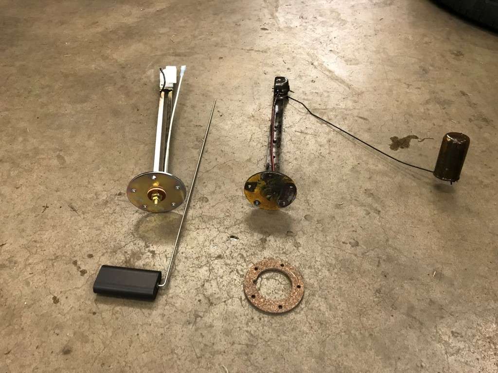
Another thing on my list of ‘things to do’ was fix the Fuel Level gauge. I had filled the tanks up and realized the gauge still read empty. Brockway used Stewart Warner gauges which in turn meant they also used Stewart Warner fuel sending units. These units are rated at 240 ohms empty, 33 ohms full. To start, I disconnected the wire on the sending unit and then checked the resistance with a multimeter. I had infinite resistance so I determined the sending unit was bad. I also checked the continuity between wire on the sending unit and the back of the gauge just to make sure it wasn’t a wiring issue either. I wound up buying a new Stewart Warner sending unit from Summit Racing for $30, part number SWW-100438...
Here are some pics of the new one with the old one...
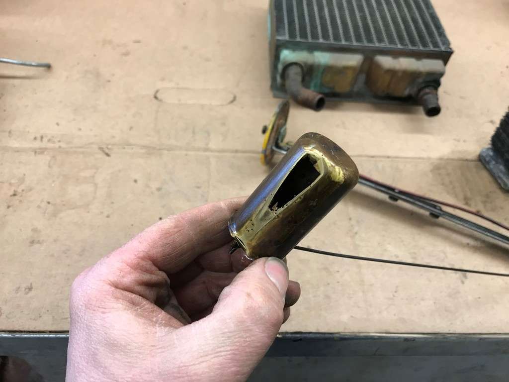
And then I found this! It looks like besides the rheostat part going bad, the float spent a lot of time sitting on the bottom of the tank!!!
The screws were a little challenging to get out so I cleaned the holes with a 10-32 tap (with some grease to prevent the stuff from falling in the fuel) and then installed the new sending unit with some new screws...
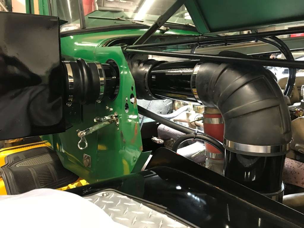
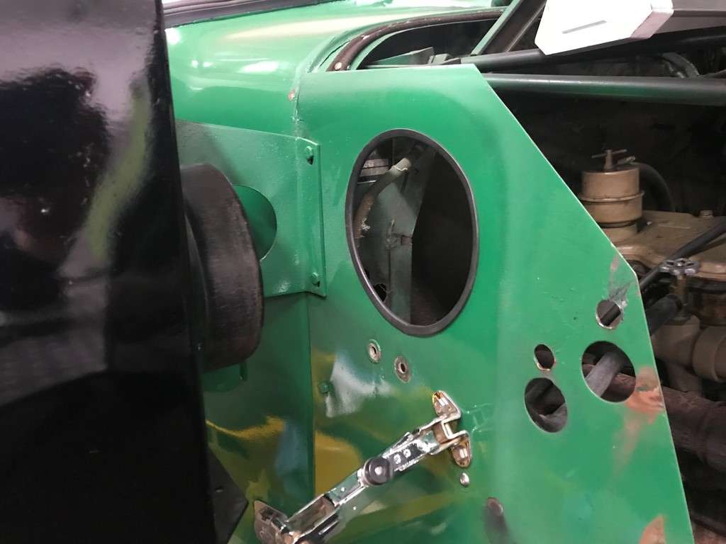
Another thing I decided to work on was the air intake tubing from the Farr to the turbo. There was some overspray on the 5.5” metal section and the rubber pieces as well...
The first thing I did remove everything and add some rubber edge molding to the hole. I usually buy this molding from McMaster Carr...
More to follow...
-
2
-
-
Here is a list I put together a while back that lists the model numbers of the various types of Brockway cabs. Not many folks are familiar with this so I figured it would help. Steve Skurnowicz provided a lot of help on this list as well...
Model 31 Trafficab with Folding DoorsModel 35 Metropolitan CabModel 41F and alphabetically lower one piece push out windshieldModel 41G and alphabetically higher one piece gasketed windshieldModel 50 is the wooden framed Deluxe cab with the three piece windshield and narrow cowlModel 51 is the model 50 with a sleeperModel 52 is the Deluxe three man cabModel 57A - 550Model 60 is the Deluxe all steel cab with the three piece windshieldModel 61A-61J are all steel sleeper cabsModel 65B - 358 & 359Model 67 - 358 & 359 3 man cabModel 68 - 360 and 361Model 75 - 758 & 759 (depending on engine) (Sheller Globe Cab)Model 76 - 758 & 759 (depending on engine) (Sheller Globe Cab)Model 78 - 760 & 761Models 50/86 - 457 & 459Models 763 / 773 / 783 / 793 - 776 (depending on engine) (Sheller Globe Cab)I can add pics if that would help...-
2
-
-
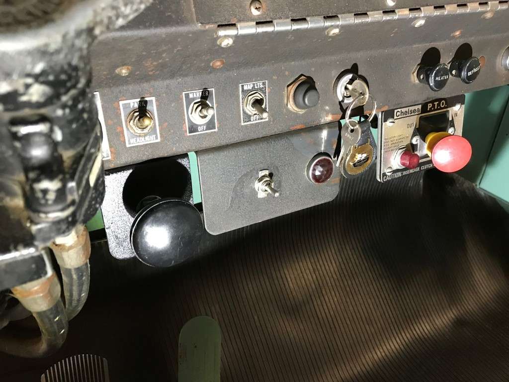
Well I have been able to finish up a few loose ends. A while back I mentioned I wanted to reconnect the existing Kysor alarm system. I was able to find the correct sending units on eBay. I was unable to find a one wire pressure switch for the oil alarm but I did find a 2 wire. All this means is that I had to run 1 of the wires to ground. On the water side, I found the correct Kysor alarm temperature switch but needed to buy a 3/8 to ½ face bushing so that the sending unit went into the water jacket far enough...

For the temp sending unit, I ran the wire in the same loom as the temp gauge sending unit. For the oil pressure unit, I ran the wire along the driver side frame rail and into the cab. Once the wires were in the cab I made the final connection to the bell. Once everything was done, I turn the key on and the light came on but the bell sounded sick. I guess from not ringing in a number of years! But after a minute or 2 it sounded much better.
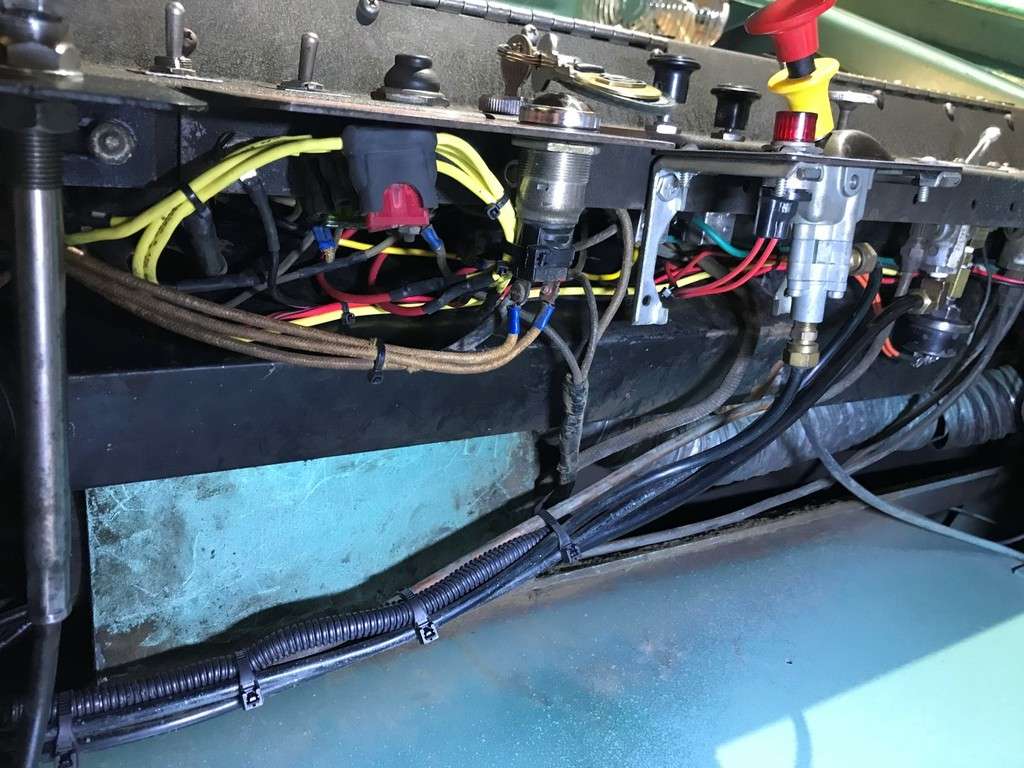
The next thing I worked on was some of the dash wiring. Surprisingly it was in decent shape but I did find a few issues. One of the circuit breakers was bad so they moved the load over to another breaker. I was able to fix that and replace the breaker. I also decided to add 4 fuses, one to replace the Jake fuse that I fed from Ignition Power, one for the PTO light that I fed from accessory power, one for a CB that I fed from accessory power, one for a future cigarette lighter that I fed from constant power. I will mount the extra cigarette letter in the glove box so that I can charge a phone, etc. when I’m at a show. Then my phone will be out of site...
This is not a great pic, but I bundled the fuses together and they fit right behind the plate with the Kysor decal...
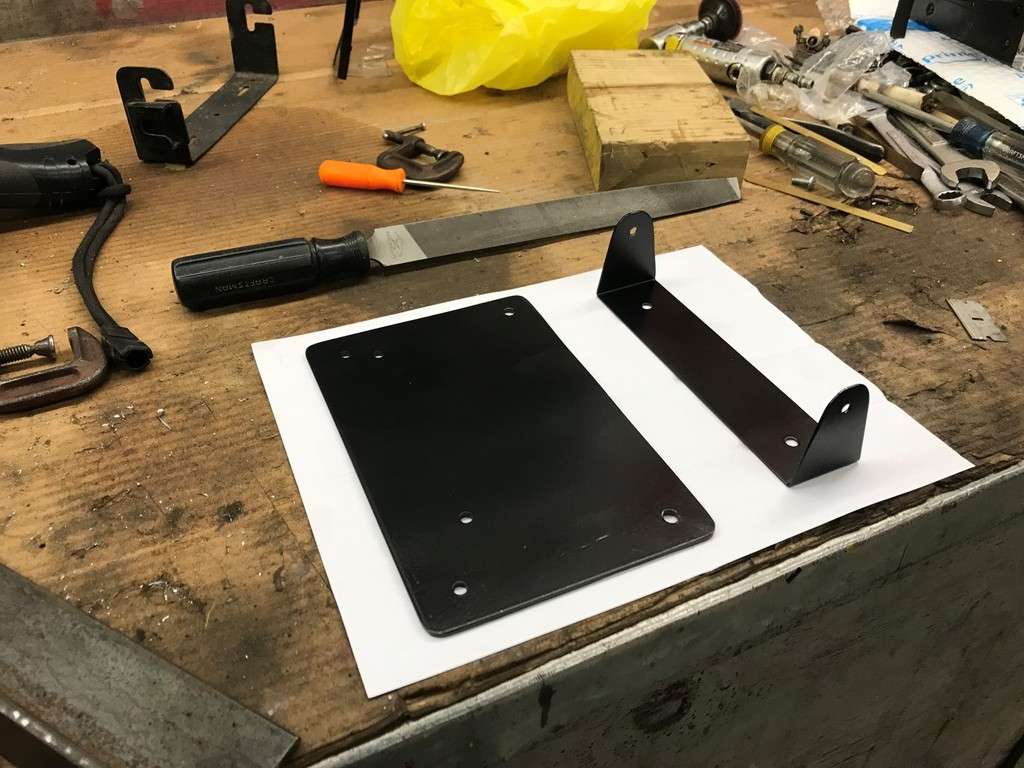
I had always wanted to put a CB in the truck but waited until now. I had a 1976 23 channel Midland that my Dad had used years ago and thought it would be ‘fitting’ for this truck. But I also thought that in the future I may want to install a newer 40 channel Cobra. Since the Midland is narrower than the Cobra and I didn’t have the original Midland mounting bracket, I made my own. I based this off of the new Cobra one I had...
Then I made a plate from some 1/8” plate that I had. I made this so the face of the CB would be flush with the dash. But I also made it wide enough to mount a Cobra in the future...
The one thing I didn’t have was a Midland mic, so I could the correct one on eBay for only a few bucks. The truck already has a CB mic clip mounted to the dash so I left that in place and reused it. And this is what I wound up with...
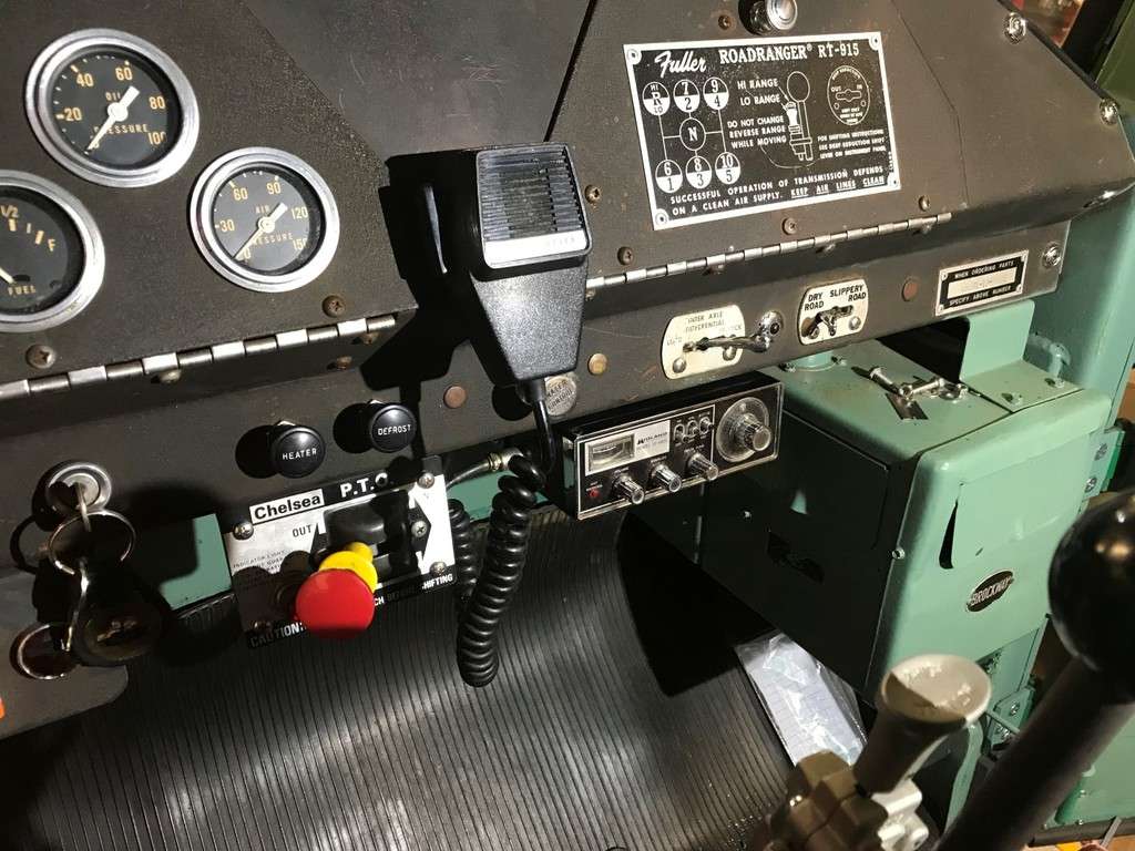
For the antenna, I decided to mount it off of the driver side mirror. On all the Brockways I have used a Kenworth antenna mount from Walcott CB, part number KWM. This is a stainless piece as well. It comes with an antenna base but in my experience they continually come loose. I usually replace these with Francis 300-CBM102 Stainless Steel CB Radio Antenna mounts. These are also stainless. The only problem is that they are no longer made in America...
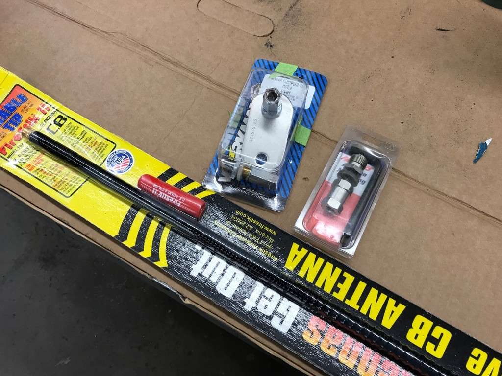

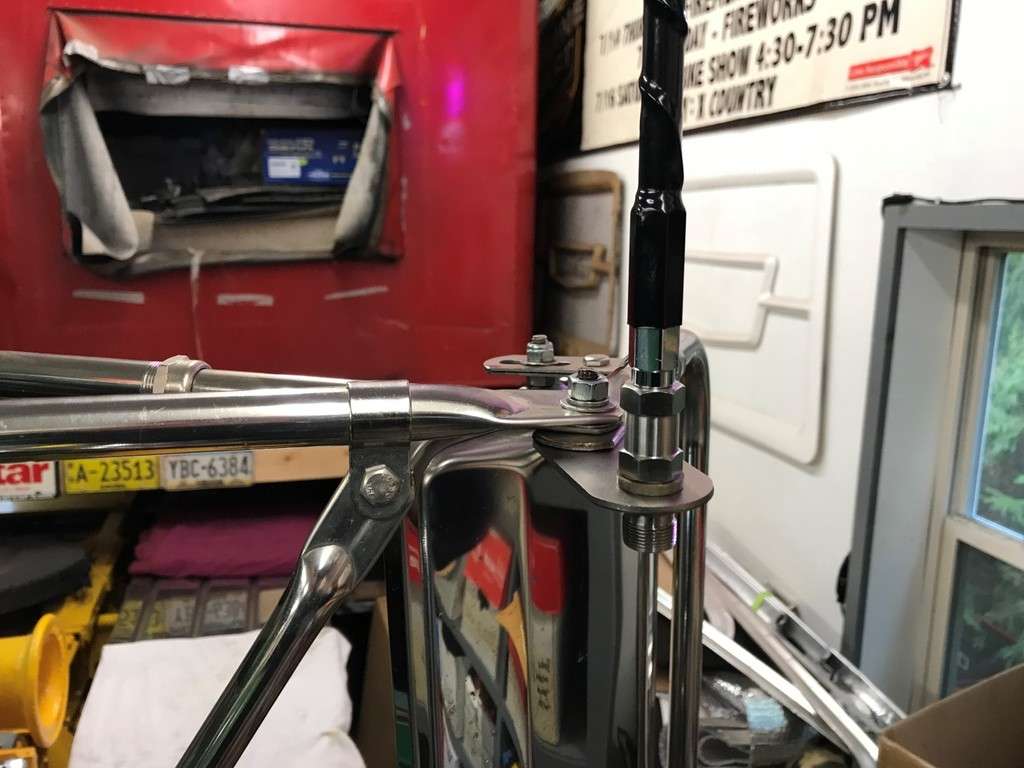
I also used a 24” black Firestik II FS2-B 5/8 Wave 300 Watts tunable tip CB Antenna. These are nice since you can adjust your SWR’s with the adjustable tip. Not terribly period correct but short and unobtrusive. Keep in mind that my Dad always carried a ‘CB box’ with him at Roadway so I spent a lot of time over the years making boxes, fixing CB mics, repairing antenna cables, etc. In fact one time he was driving under a bridge and lighting hit the bridge and transferred over to the CB antenna and into the CB. It actually shut the truck right off but he was able to restart it. It destroyed the antenna and cable but all it did was blow out the diode on the power side of the CB. These are the diodes they use in case someone reverses the polarity on the CB when they connect them. I still have the fried antenna cable in the garage
")
That’s it for now!
-
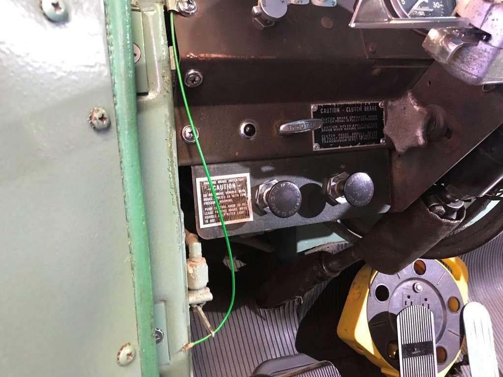
In another post I had asked about the correct location for the Jacobs engine brake switches. Some folks have them mounted on the passenger side of the dash but the most common place seems to be on the left side of the speedo and tach. I also have a 1974 300 series dash and it has a blank plug in this place along with a blank fiber optic tag. So I decided this was the best location. I also was able to find the correct older switch plates. These came from Courtland Truck Works who specialize in Peterbilt restorations. I taped them in place first...
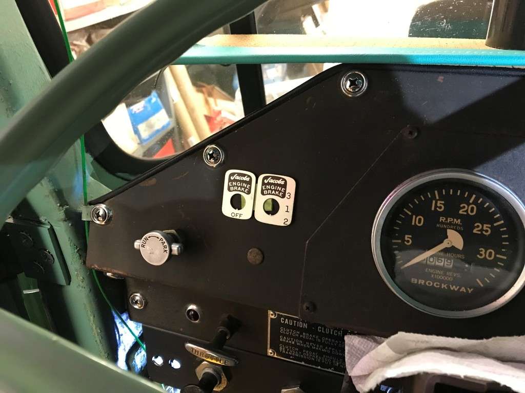
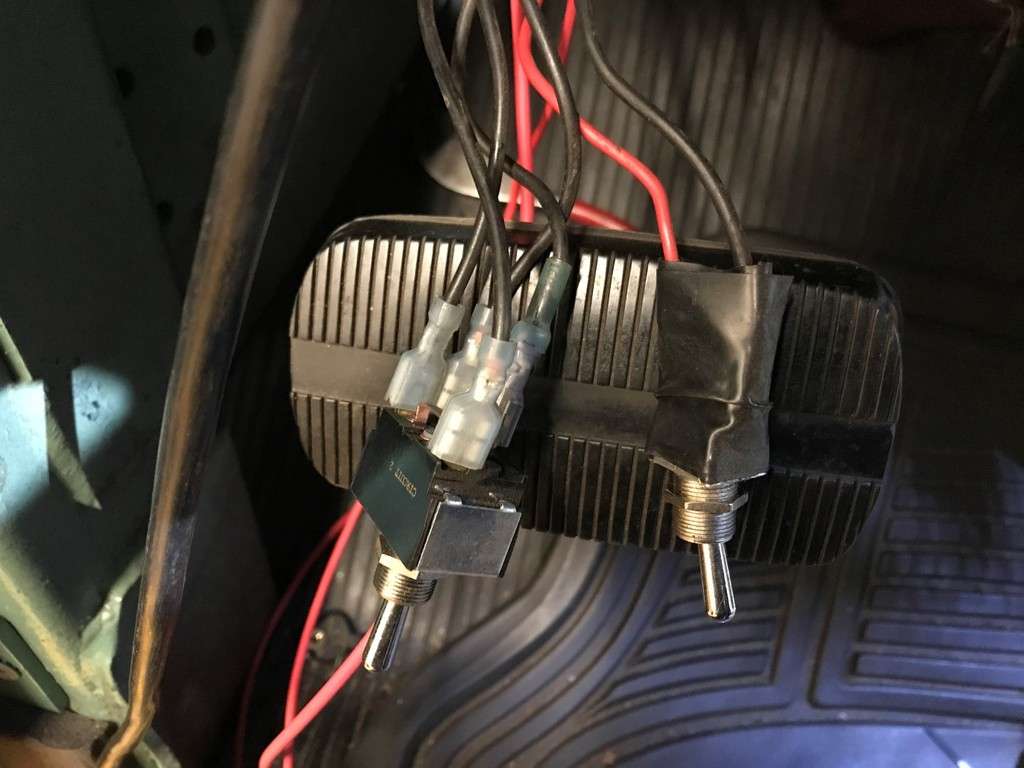
The switches were originally mounted very tight to the tractor protection valve and this is how they were wired so I corrected this as well...
And this is the finished product...

I’m happy with this location and it matches were I put the single switch in my Dad’s 361.
I also dug out the original protection valve dash plate from my Dad’s 361. This still was in decent shape and had the factory decal on it as well...
And I wound up replacing the original plate that had the extra holes drilled in it for the switches...
Well that’s it for now...
-
2
-
-
- Popular Post
- Popular Post
Thanks Bob!!!
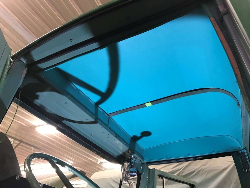
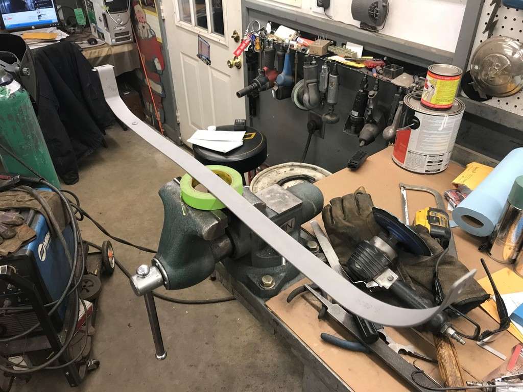
Last week I painted the metal support back for the headliner...
And last weekend I was able to reinstall it...
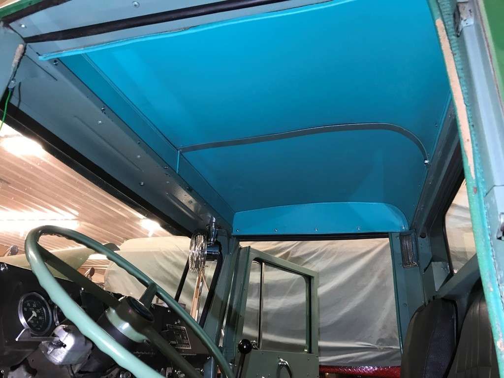
So it looks like I’m done with the headliner. Then I turned my attention to the dash...
The truck had a mismatched tachometer in it but I was able to find this setup on eBay in December of 2016...
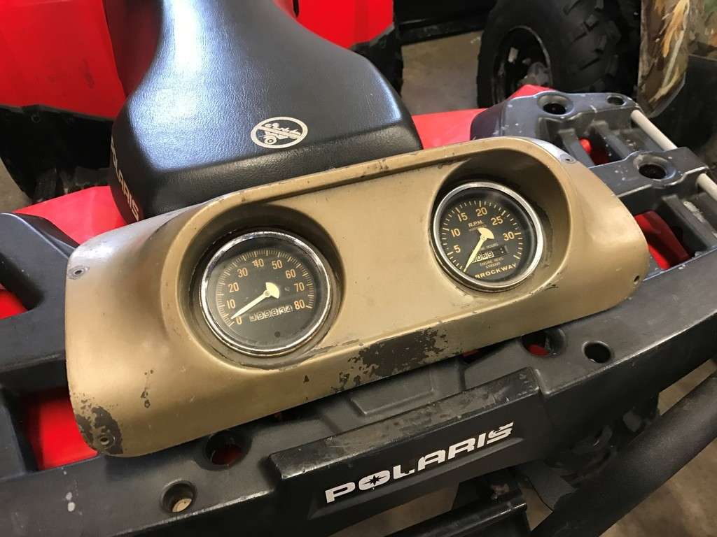
The bezel needed a good cleaning so I taped it off to prevent and damage to the glass, etc...

This picture was taken on January 7, 2017, my Dad’s 78th birthday. I had my Dad clean the gauge for me and install it in the original panel. Not much else to say except I really miss having him here with me...

More to follow...
-
3
-
1
-
So my last roadblock was to try to figure out what to do with the seam in the middle. I was able to salvage a few small scraps of fabric from these pieces...
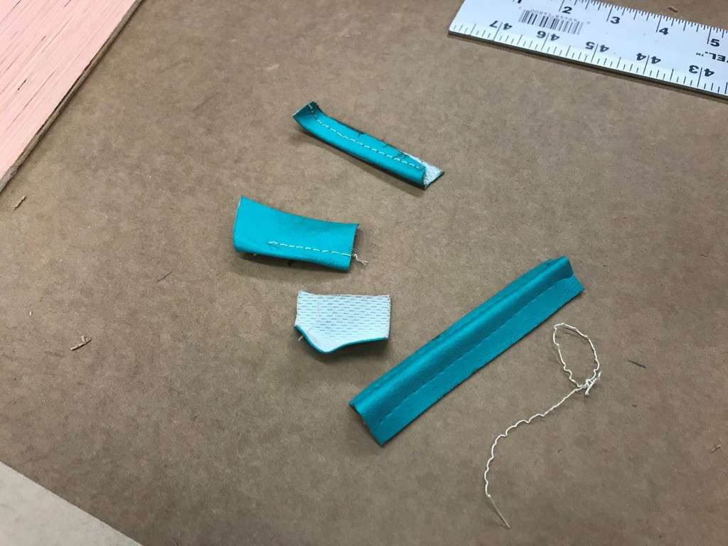
Using one of the scrap pieces, I glued it to a pieces of 1/8” aluminum and then clamped it overnight...
 L]
L]
It looks dirty but it did clean up well. The next day I screwed it in place with some #4 SS screws...
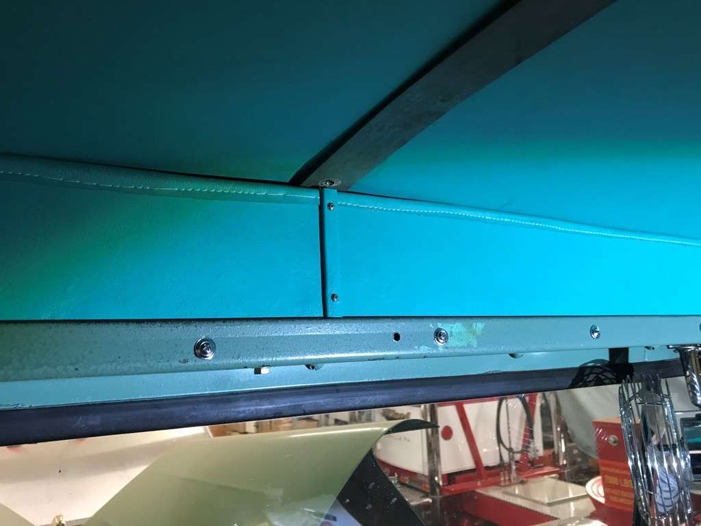
And this is what I wound up with...
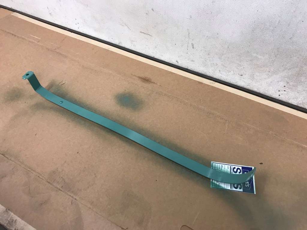
The last piece of the headliner I needed to fix was the center bar that holds the headliner in place. Russ told me that when he got the truck there was an antenna mounted in the middle of the roof and they drilled a hole right through the center of this piece...
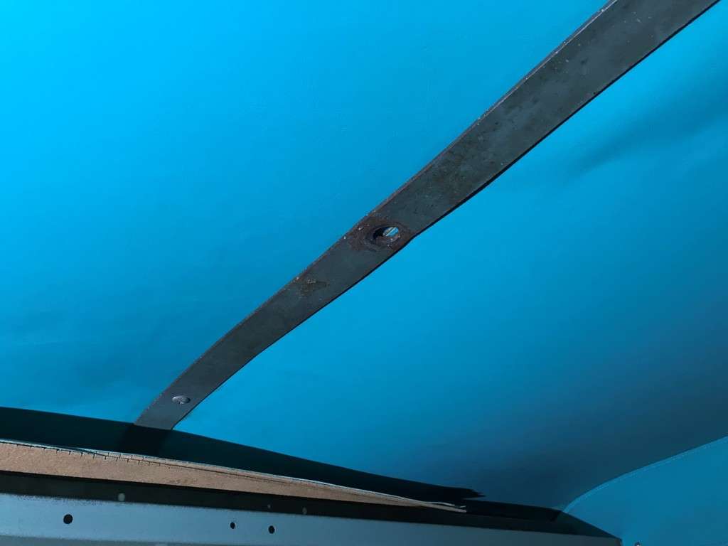
Well almost the center of the piece...
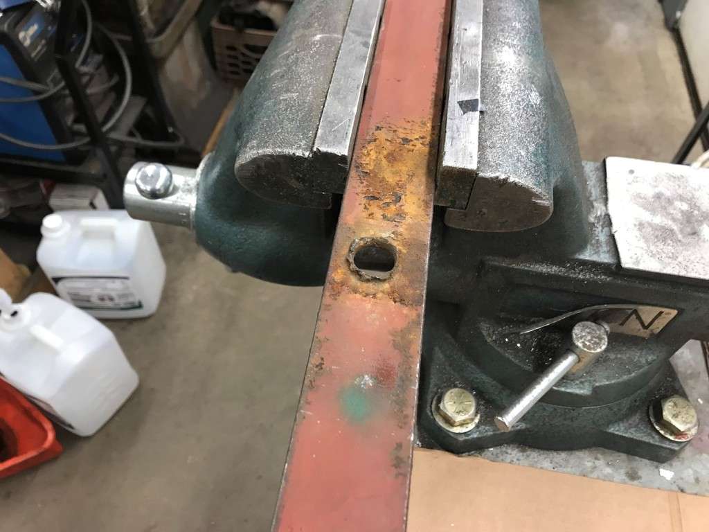
I cleaned up the hole with the angle grinder and the cut a piece to fill the hole in...
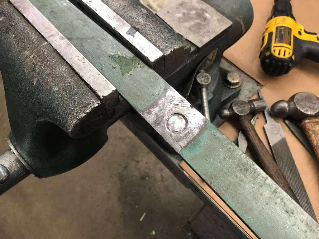
Then I was able to weld the plug in and grind it smooth...
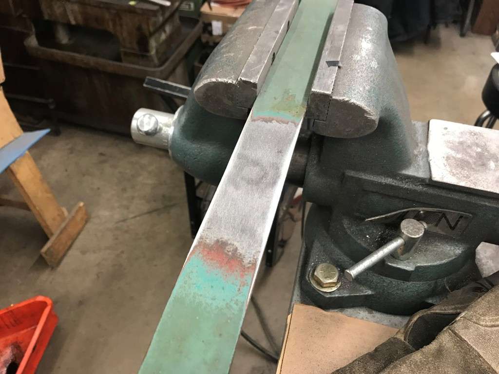
And then I sandblasted it...
I gave it a few coats of DupliColor’s Detroit Diesel alpine green and should be able to install it this weekend!
That’s it for now!
-
1
-
1
-
-
Once the headliner was down I found a few wiring issues (and a handful of plastic hitch hikers!!!)...

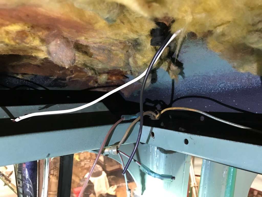
One thing to mention with the cab lights is that the 3 middle lights are controlled separately from the 2 outer. I used a factory early 358 wiring schematic to help me figure out a few wires.
I like to crimp, solder and heat shrink all my connections so I decided to fix the wiring while I was at it. I also added grommets to each of the holes the wires passed through for the cab lights. Once I was done with the wiring I reinstalled the headliner with the new screws. There were also 2 pieces that were made to fit in above the front ‘package’ tray. I’m not really sure how these were made to fit so I decided to make them work regardless. My first though was to install them on the outside of the lip just like the side pieces. I also did this on the 155W and my Dad’s 361.
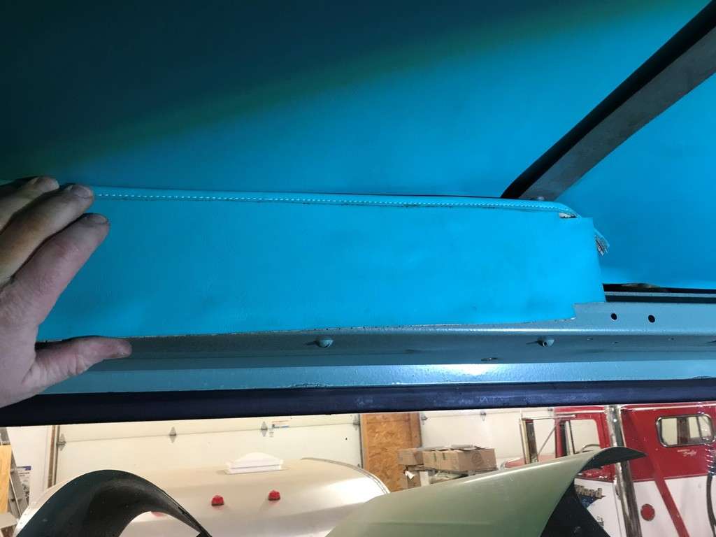
But there wasn’t enough material to wrap around the bottom of the fiberboard it was glued to. It’s my understanding that these were originally installed behind the lip.
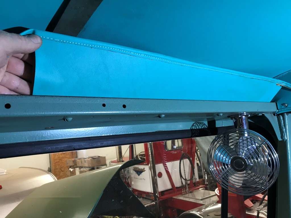
I decided my best option would be to glue these to a piece of luan...
These pieces are tapered, meaning the middles are taller than the ends. So I had to cut these ends off...
Once the luan wood was trimmed to fit I used some Gorilla glue to attach the fiberboard to the luan and then clamped it between 2 pieces of wood...
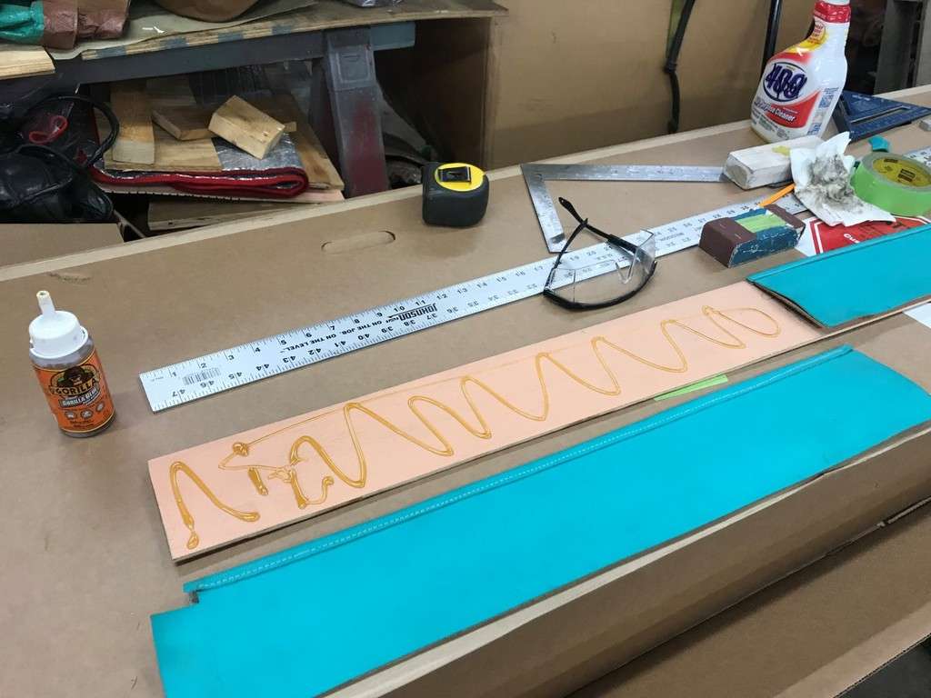
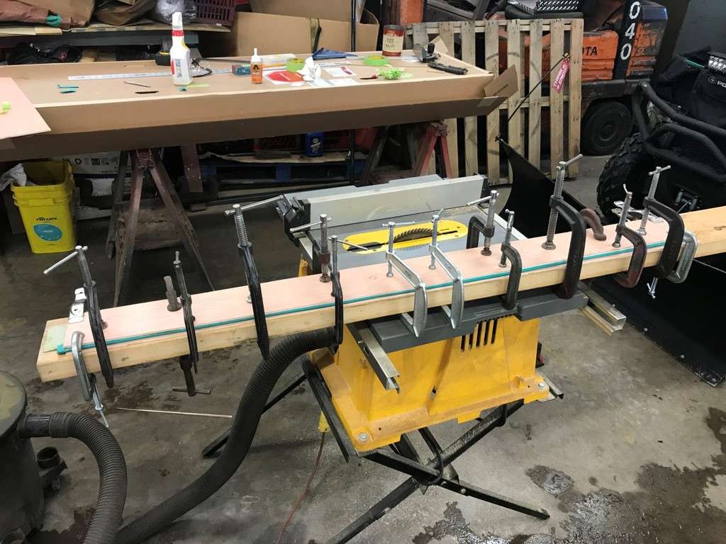
And this was the end result...
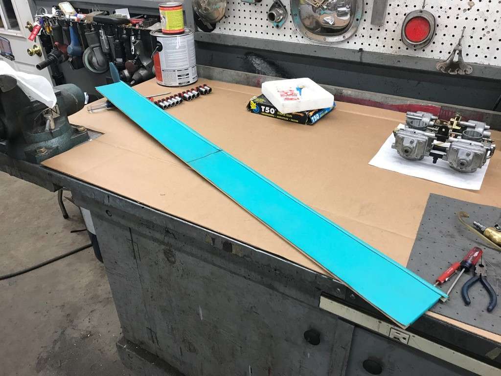
More to follow...
-
1
-
-
Paul, both the 270 in the 68 Brockway and the 335 in my 76 Brockway have compression releases...
I wound up using a large black knob I had and it pulls fine. Our 761 has the same knob in the dash and that’s what I based this on. I wound up using a stock plate from a dash I bought from the junkyard a few years back. The dash wound up in my Dad’s 361 since it was pretty much original without a ton of extra holes drilled in it...
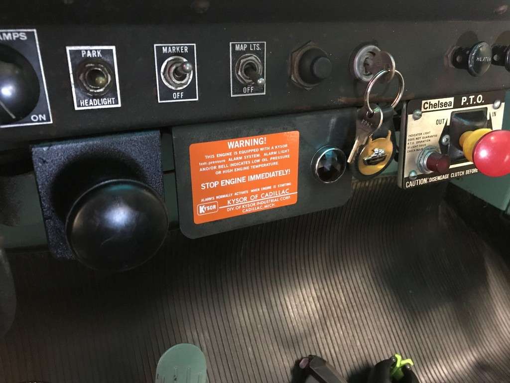
In the pic above you can see the plate with the large lamp for the Kysor system. Long after the decal fell off a hole was drilled into this plate to mount a switch to control a fan. I wanted to bring it back to original so I removed the plate and welded the hole in, being careful not to generator too much heat to burn the original dark green paint...

Once I was done filling the hole I painted the area front and back and dug out one of the reproduction Kysor decals I had made a while back...
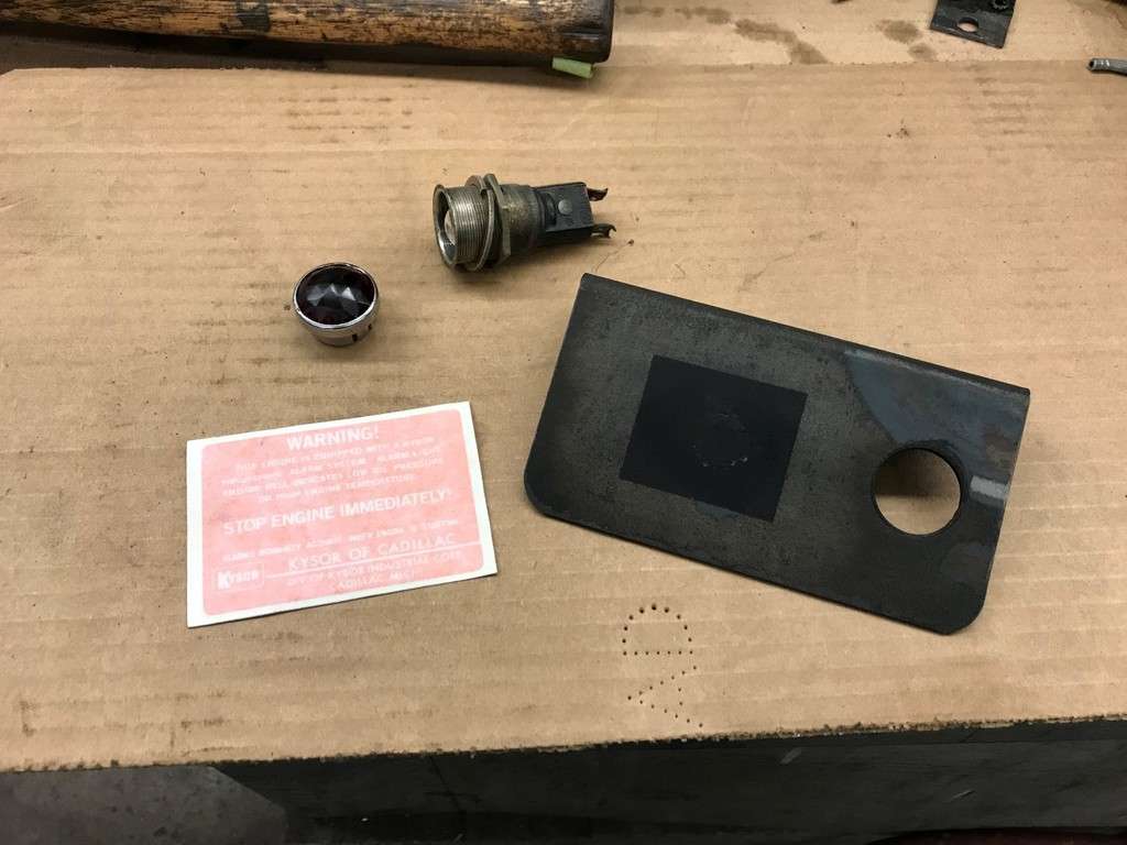
And here is the finished product back in the truck...
As you can see this is drifting from my power steering install but that’s ok...
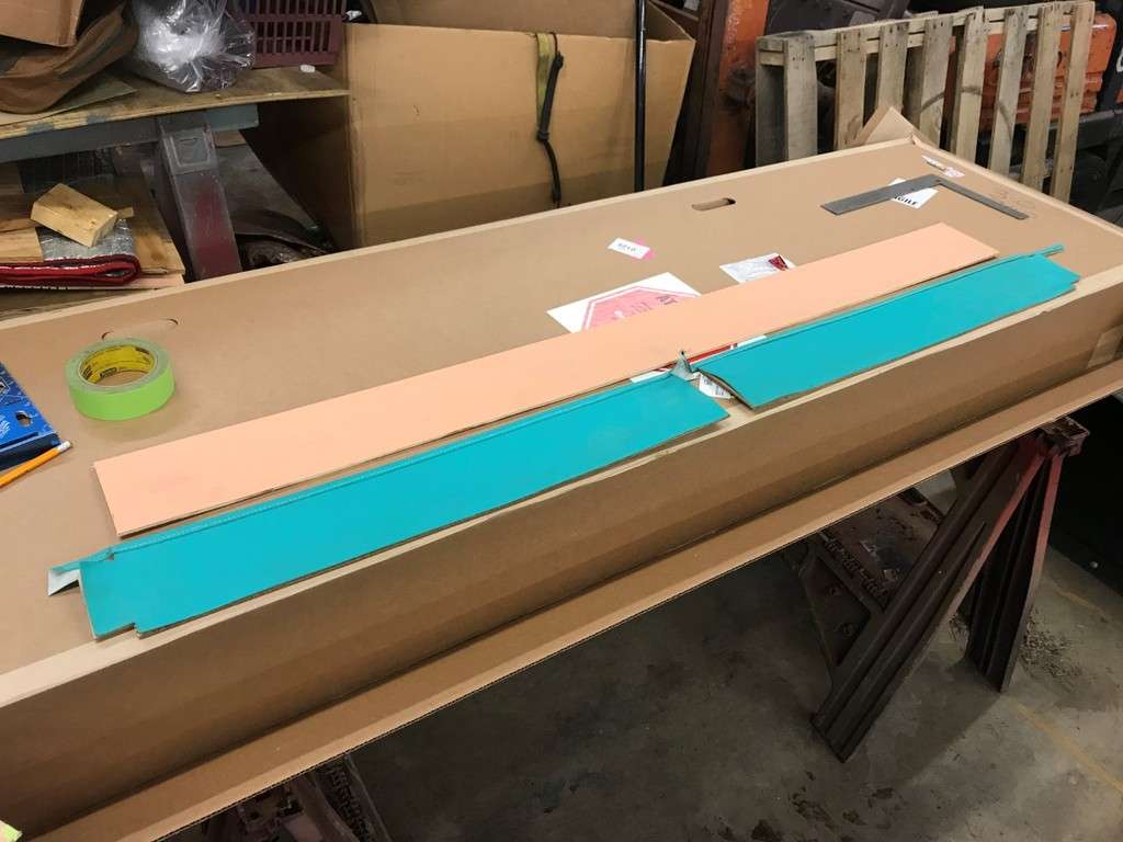
The next thing I decided to work on was the headliner. Russ had a guy in Saylorsburg make a new headliner based on the original pieces he gave him. He had a hard time getting it to fit well so I figured I would tackle that next. For hardware, someone had installed 6/32” rivnuts in the mounting holes. These really don’t work well for this application since the screw needs to float a bit in the hole. Some of them were cross threaded also (probably because of the installation tool) so I drilled them out. I replaced them with this Balkamp #8 U spring U nuts, part #665-1955.
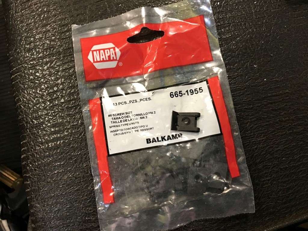
For the screws, I was also able to pick up the correct screws from Napa, but I have to dig up the Balkamp part number. But they are the same as these Dorman 961-235 screws...

More to follow...
-
1
-
-
-
-
-
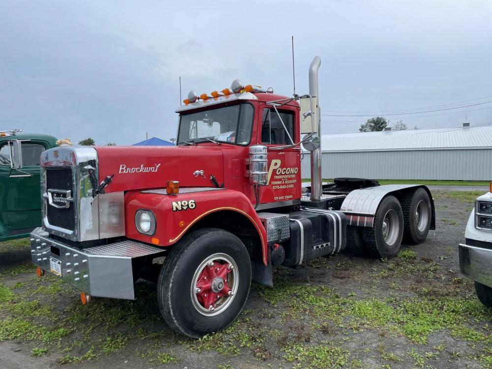
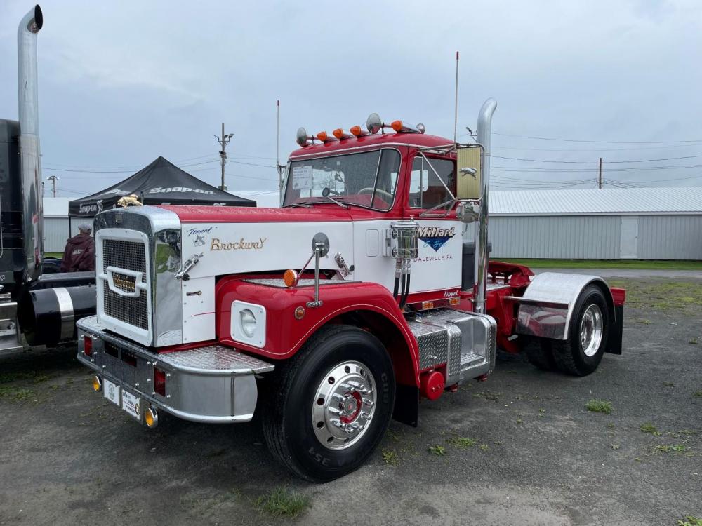
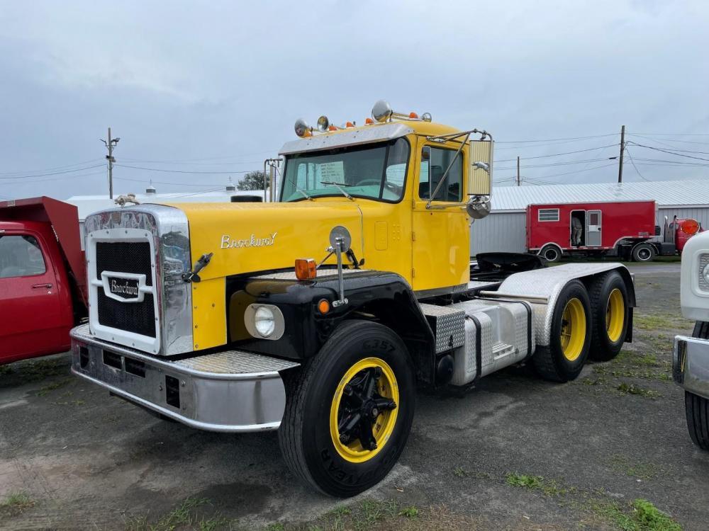
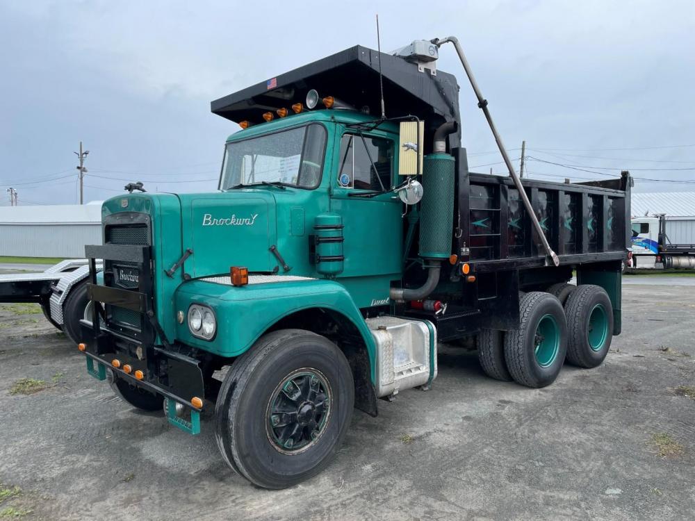
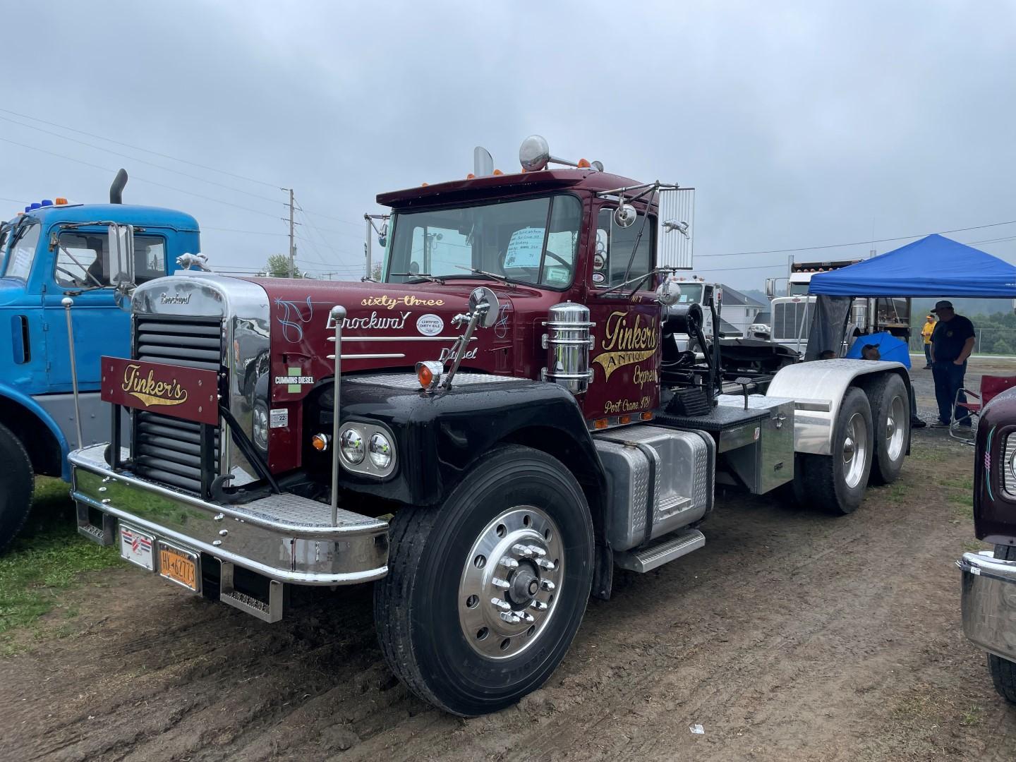
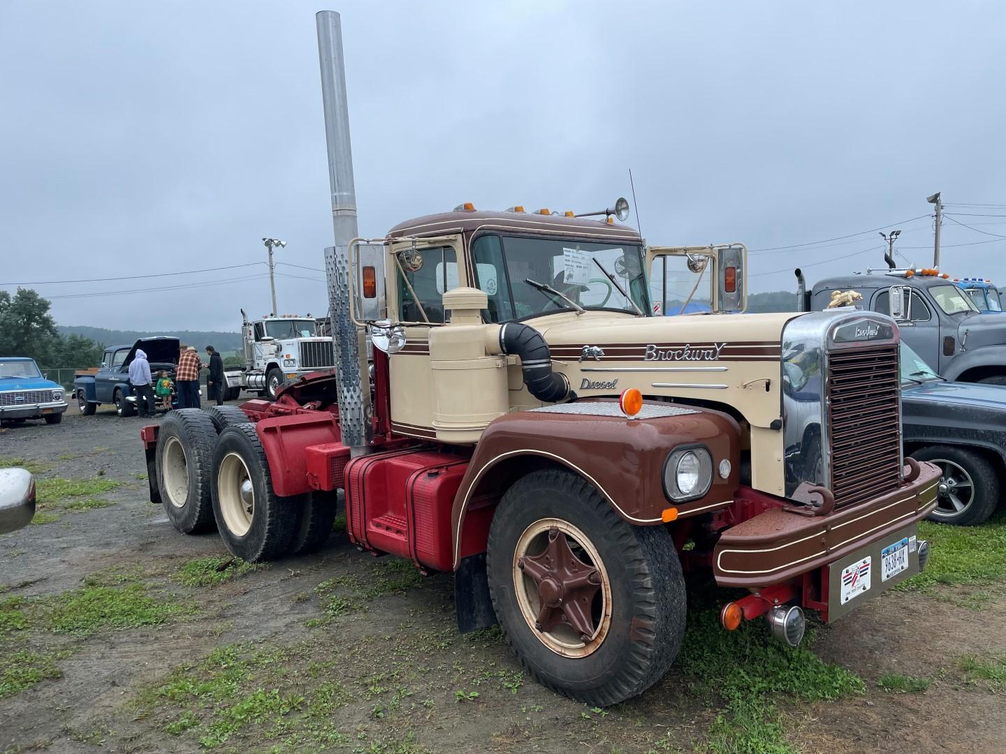
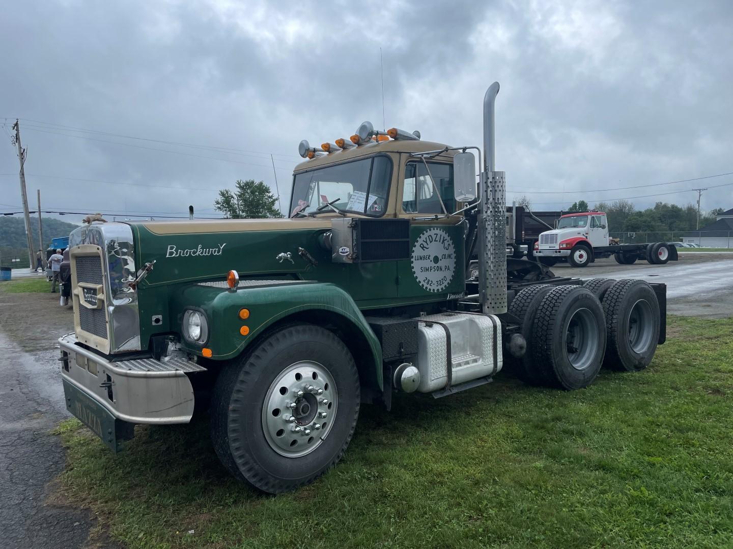
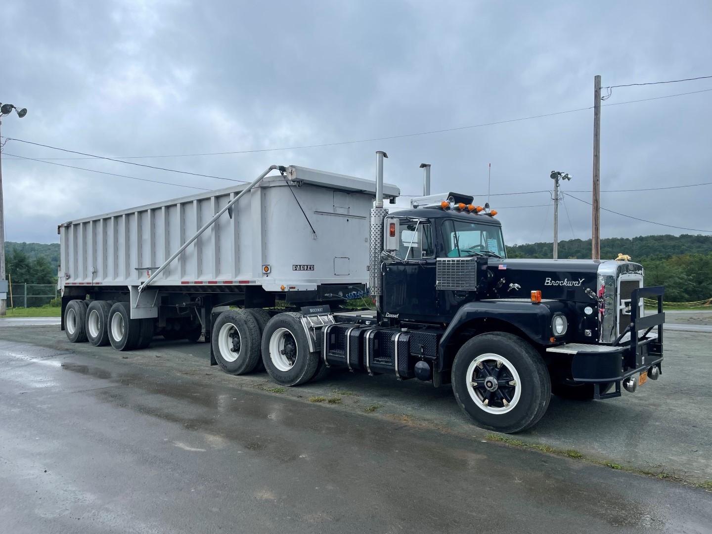
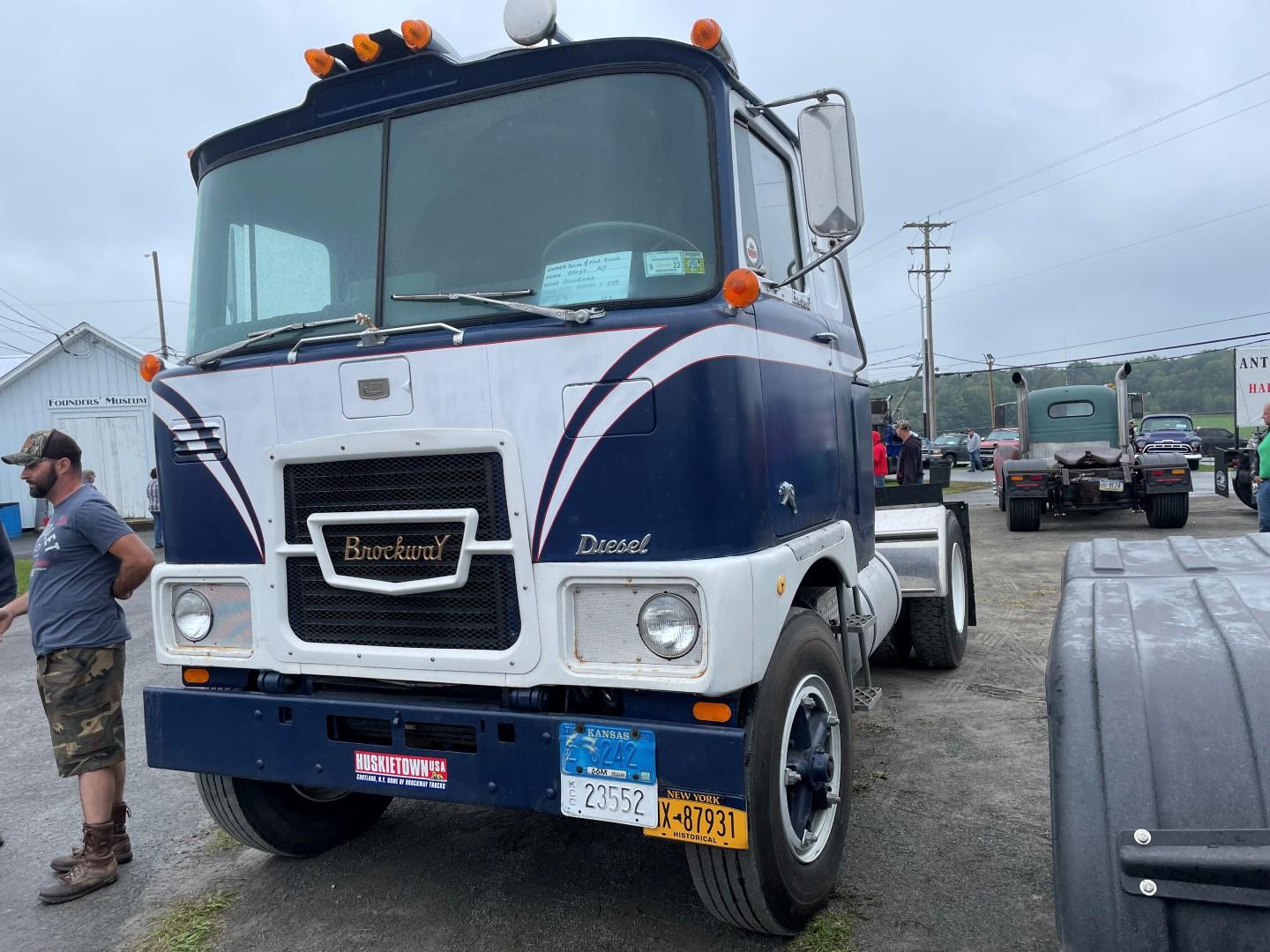
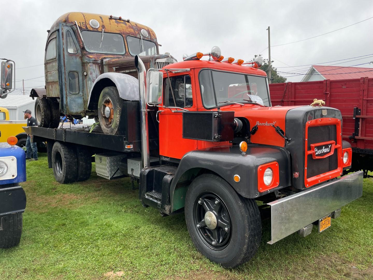
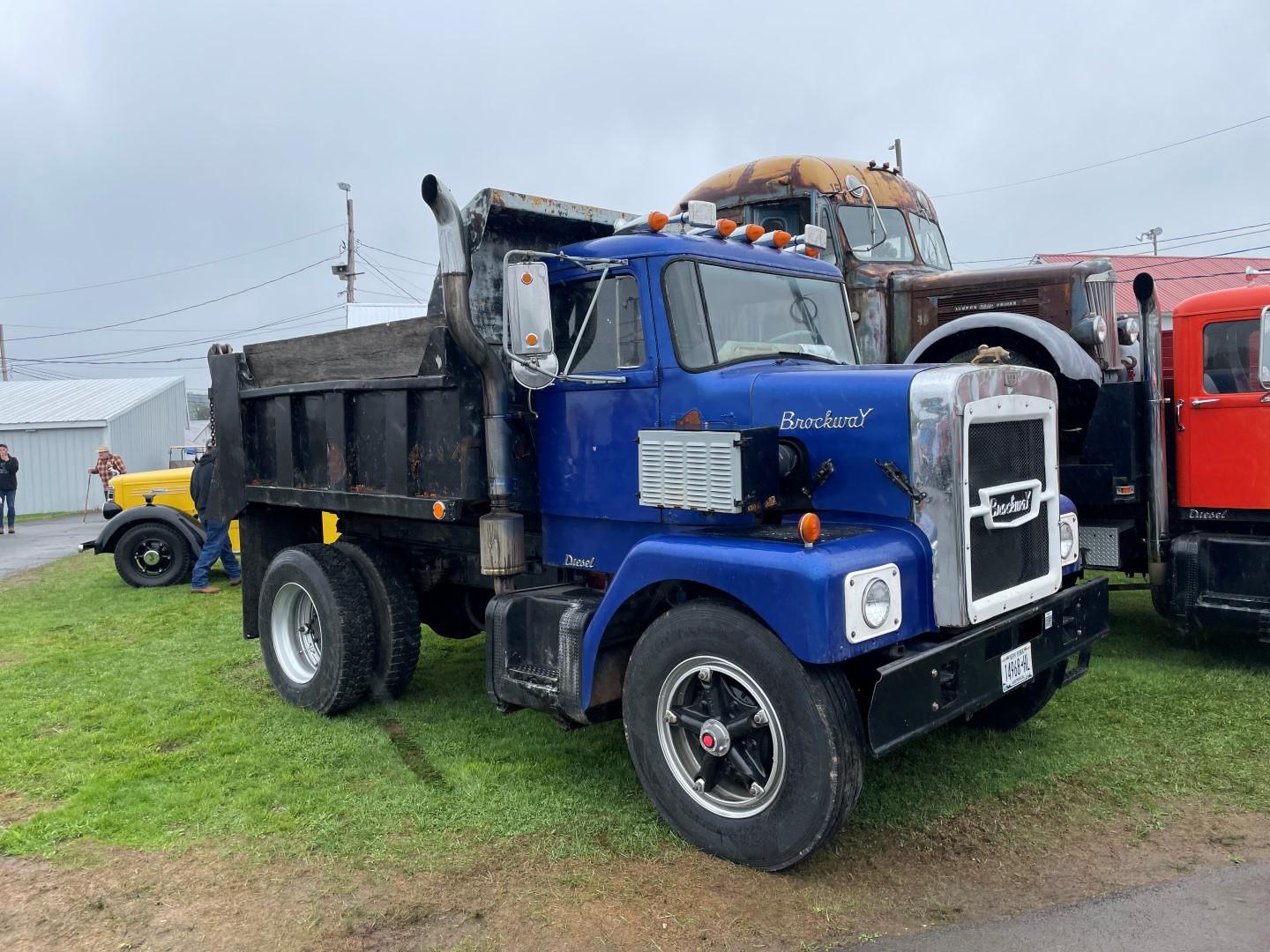
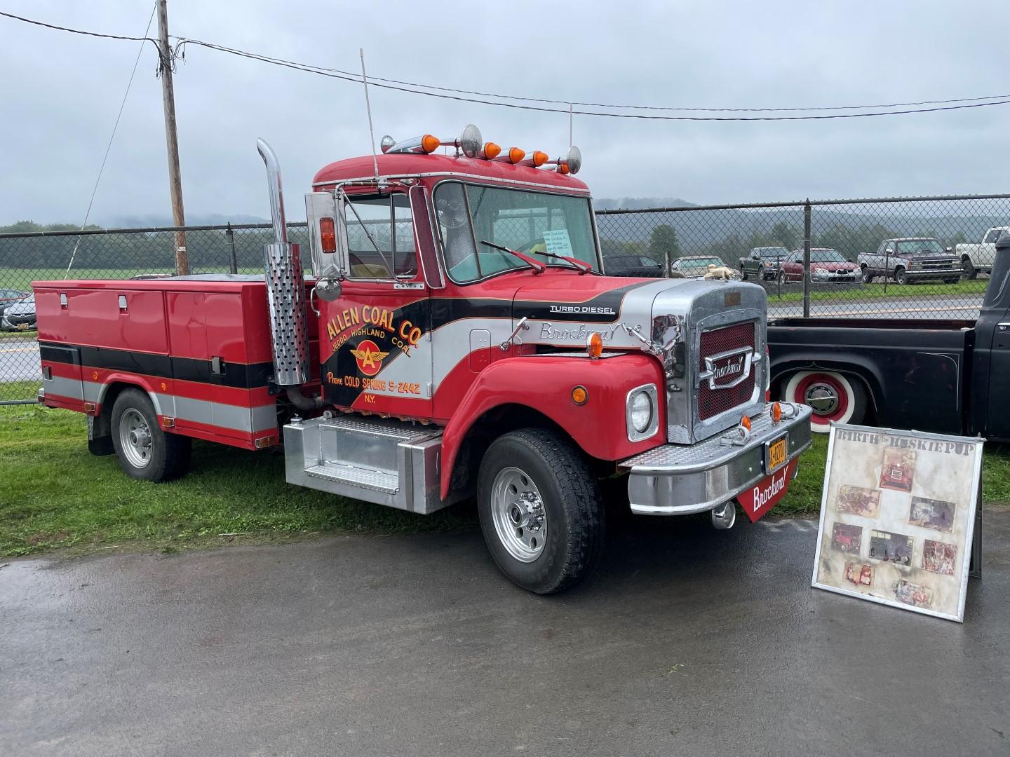
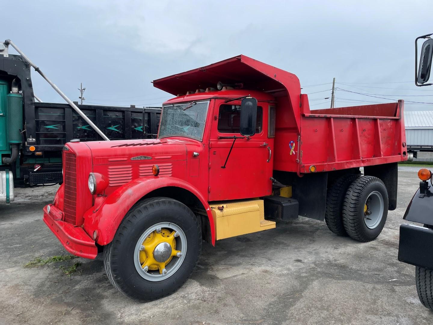
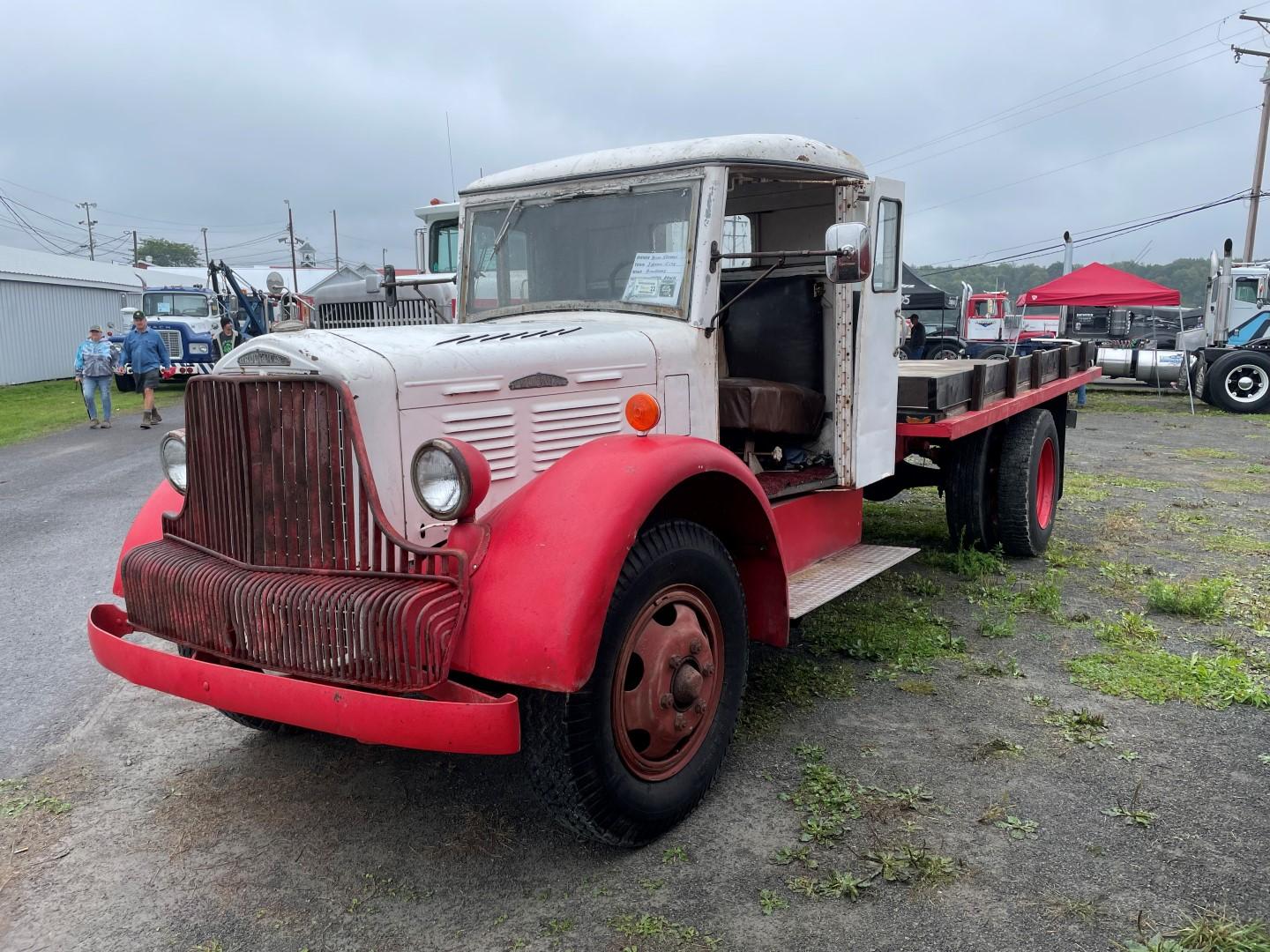
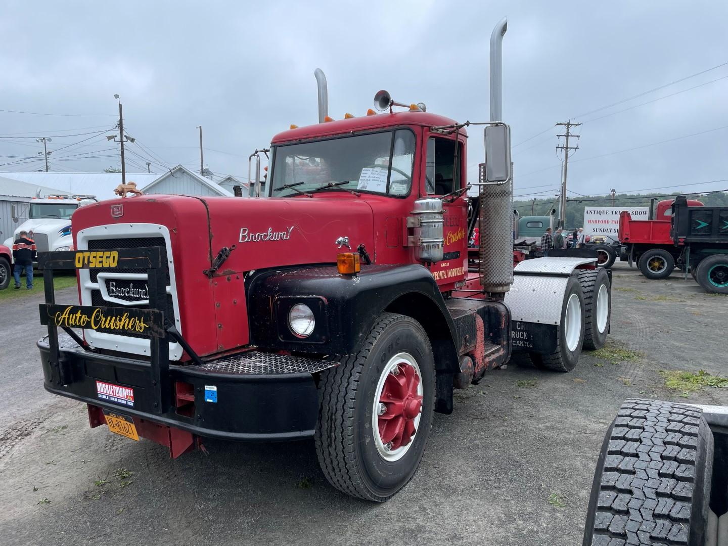
This past Sunday our local ATCA club had our annual truck show and the Harford Fairgrounds. Harford PA is about halfway between Scranton PA and Binghamton NY. Even with the soggy weather we had 110 trucks and a great turnout of Brockways. Here are some pics from the show...
-
2
-
-
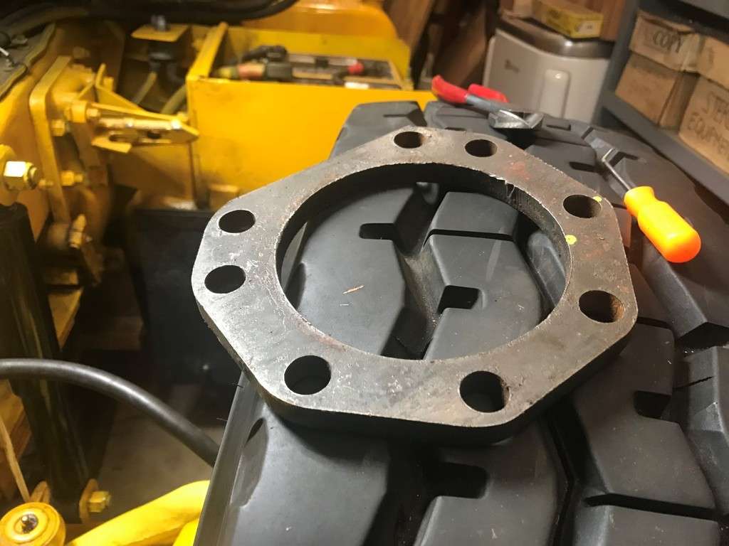
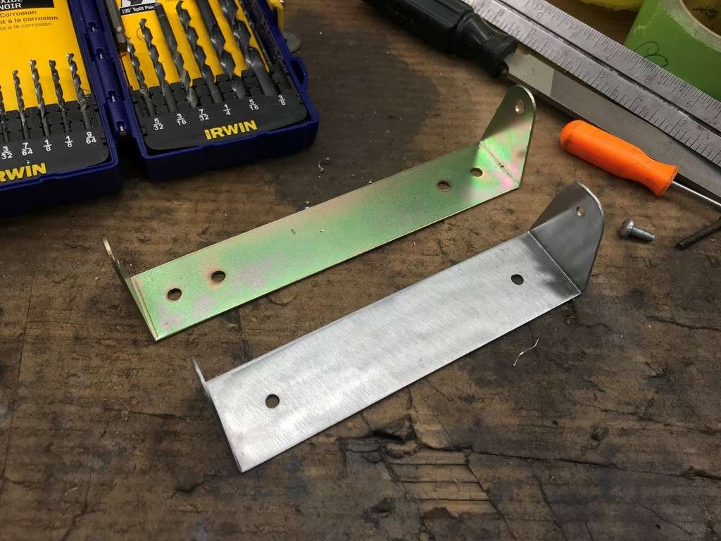
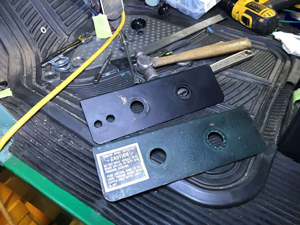
While I was working on the compression release I decided to replace something else. The fan support bracket that is mounted directly underneath the compression release bracket had (3) separate spaces under each bolt to compensate to the jake height. I decided to remove these spacers and make (2) new ones...
This is what I started with...
And these are what I made...
And here they are installed...
Well that’s it for now...
-
1
-
1
-


BMT Forum Logo

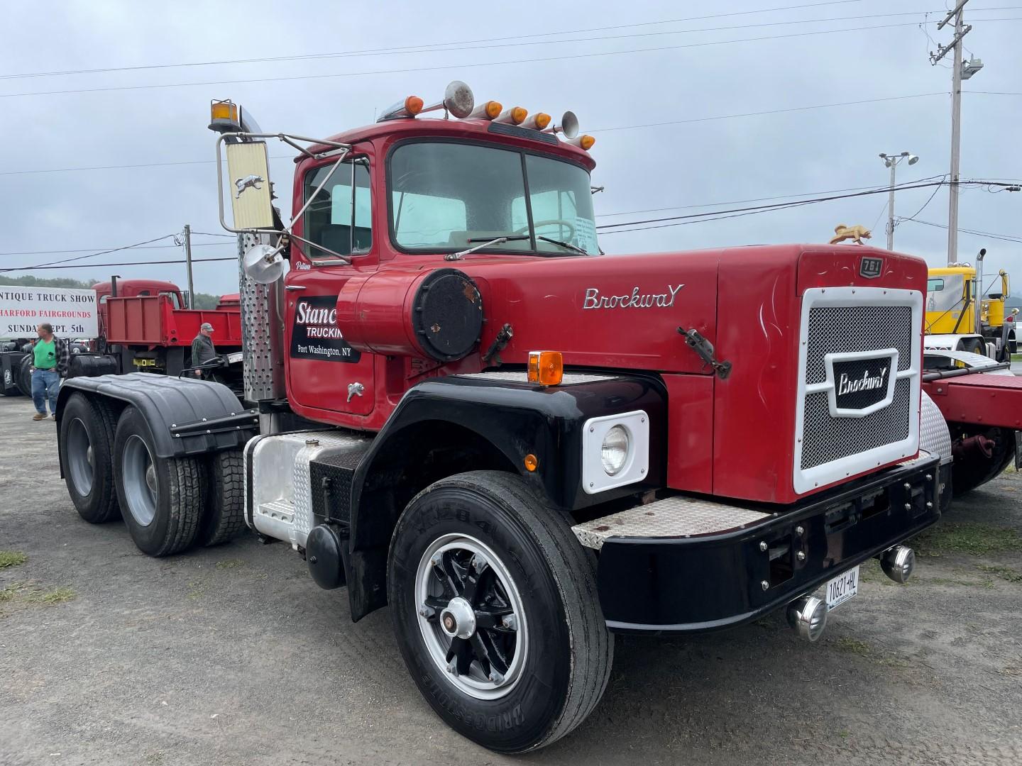
1955 Brockway 155W Continental to Cummins
in Brockway Trucks
Posted
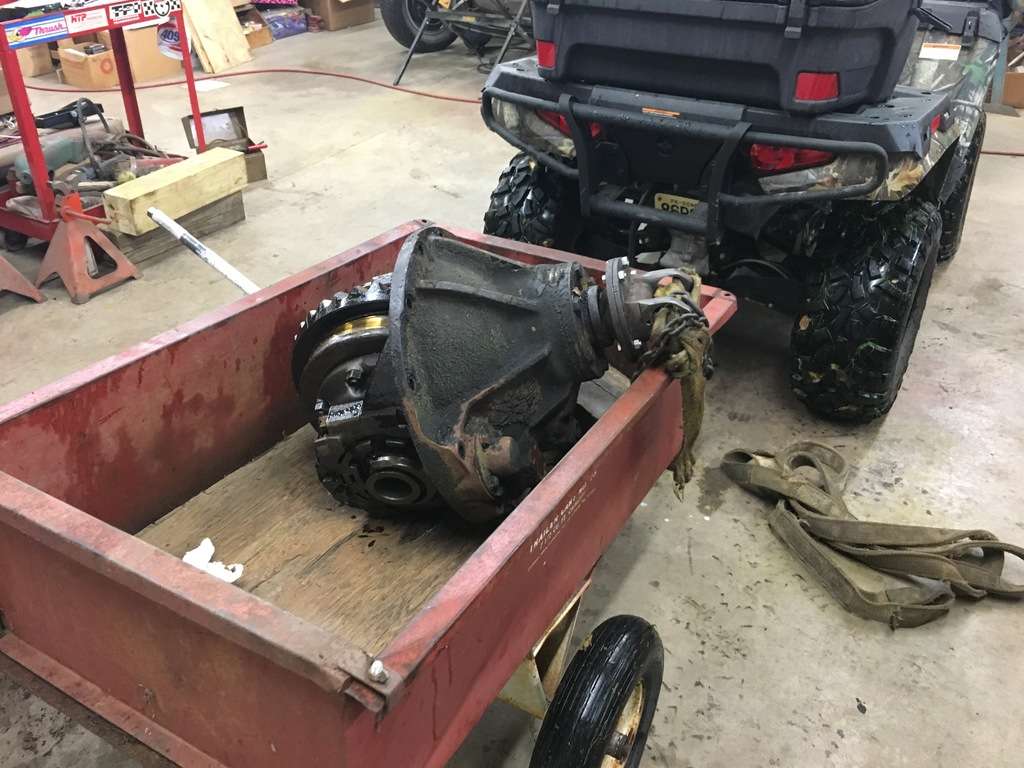
After everything was cleaned up, I realized the ratio was actually stamped on the carrier. Before I thought the only way to identify the ration was by looking at the head if the pinion when the number of ring and pinion teeth were stamped. Here is a quick sketch of where the numbers are on the carrier... When I called around everyone asked for the casting number, 28656, which refers to a ribbed carrier.
The following day was supposed to be warm so I dug out all of the paint supplies and figured I would shoot the rear outside. But I wanted to clean the inside one more time before paint. Also, when I originally pulled the carrier, the back lash felt good and the ring gear looked good. So I lifted it up in the air one more time to check the back lash with a dial indicator. As I was rotating the ring gear I was looking up towards the pinion (which is sort of buried in the carrier) and caught a glimpse of something that looked BAD. At that point I decided to pull the pinion cage to get a closer look...
Damn... I still can’t believe that I didn’t feel this in the back lash but these things happen. I also didn’t see any chuck in the bottom of the housing (and I wasn’t really looking either...) since it was raining pretty good and we were trying to get out of the weather. Should I have looked at it better before I cleaned it? Sure, but hey these things happen...
So at that point I started looking for another set of gears. But at least this time I had more information, like the Eaton number on the ring gear, 41962. After a quick Google search of this number, I found a set of gears in Toledo OH (same place that had the carrier years back). They listed the ring gear as 41962 and the pinion as 48820. This is when I posted a wanted ad on the message board hear and well as on a few groups on FB.
More to follow...