


Dtech
-
Posts
29 -
Joined
-
Last visited
Content Type
Profiles
Forums
Gallery
Events
Blogs
BMT Wiki
Collections
Store
Everything posted by Dtech
-
E7 low power help!
Dtech replied to Dtech's topic in Antique and Classic Mack Trucks General Discussion
Has anyone ever had a Ecm being the root cause of low power? I do not think it is the issue but maybe it is? I wish I had a test ECM or maybe I could sent it to someone and see how it ran on there truck? -
E7 low power help!
Dtech replied to Dtech's topic in Antique and Classic Mack Trucks General Discussion
Thanks FJH for your advice, However I am a little loss on the FAC I know the older mechanical injection pumps had them. I can not find anything like that on this pump? It only has wires going into the back of it. It has no lines from the intake manifold to the injection pump. It also does not have a Boost psi sensor that I can find only intake air temp that is also the only sensor that is in the manifold. It does have an air line for the air compressor inlet but no leaks on it that I can find. -
E7 low power help!
Dtech replied to Dtech's topic in Antique and Classic Mack Trucks General Discussion
Great Thanks 1995 E7 in a Ch613. -
E7 low power help!
Dtech replied to Dtech's topic in Antique and Classic Mack Trucks General Discussion
Yes I am using the turning tool in the flywheel housing, yes I am turning it the direction of rotation I am not having any trouble setting the lash or checking it. I am going by the book always do. I was just confused my the increase in the lash that is not common in Diesels. I am a 35 year diesel tech not my first rodeo lol. This E7 just has me scratching my head. Does anyone know the answer to my fuel psi ? I need to rule it out Thanks -
E7 low power help!
Dtech replied to Dtech's topic in Antique and Classic Mack Trucks General Discussion
Original Cam and Cam gear was used with the original key. This makes sense with the Engine brake, since the compression brake has no Injector rocker arm to be the slave it has to use another cylinders exhaust rocker arm. Yes it is a Dyna Tard. Thanks for clearing this up. Does anyone know if 26 psi at the Injection pump is enough fuel psi? -
E7 low power help!
Dtech replied to Dtech's topic in Antique and Classic Mack Trucks General Discussion
We are back on this project today I have a Question for you E7 Mack experts. We checked the valve lash using the procedure in the book, however we noticed that when the intake valve is fully open on a cylinder the Exhaust valve on the same cylinder has lots of lash! This means that Mack does not adjust lash on the base circle of the camshaft lobe or we are out of time. Has anyone with experience ever noticed this? Just to be clear if I turn the Crankshaft in the direction of rotation to the cylinder marked on the flywheel 1-6, for example, that lash is correct however if I keep rotating it to the next set to be adjusted, the lash becomes larger than 0.024 around in the .060 thousandths on that previously adjusted exhaust valve? It will keep that gap through out the intake stroke and comes back to the .024 right before TDC on the compression stroke. Is this normal? I also noted that this only happens on the Exhaust valve the intake lash remains the same through out all stokes other than the intake stroke of course The mechanic that built this motor told me he had installed a used Crankshaft. He had to change the Crankshaft drive gear due to size deference, the new use crankshaft had a larger gear on it !!! so he swapped it with the original drive gear. I did check crankshaft to camshaft timing using the book procedure it seem to be on the money, I also did notice that Valve overlap is happening on TDC. I also double checked flywheel to crankshaft timing by pulling the nozzle on #1 cylinder and confirmed TDC #1 alines with TC mark on flywheel. Thanks For your help -
E7 low power help!
Dtech replied to Dtech's topic in Antique and Classic Mack Trucks General Discussion
Okay I finally got my old Prolink from E bay Can could watch the torque limit derate. It was not programmed for it and the switch is in the off position. Prolink did display 100 load and 100 throttle on the test drive fuel quantity went to 145 no valve given just a number I am not sure what this means maybe someone does? Travel of the fuel rack in mm? I am wondering about fuel nozzels the owner has no idea if they were changed I am trying to get a answer out of the mechanic that rebuilt the motor. Could a guy have installed nozzles that would cause this low of power? Can anyone confirm if 27 psi under load is a okay fuel psi. -
E7 low power help!
Dtech replied to Dtech's topic in Antique and Classic Mack Trucks General Discussion
Joey Back in the day when we had green screens and C : dos. computers lol. Can you change parameter's like the torque limit derate on an ecm with one? I am hoping it at least gives me more info to watch, -
E7 low power help!
Dtech replied to Dtech's topic in Antique and Classic Mack Trucks General Discussion
I am leaning towards the ecm as of Right now I should get the prolink 9000 Monday to hopefully watch The Torque limit value. I will keep you guys informed. -
E7 low power help!
Dtech replied to Dtech's topic in Antique and Classic Mack Trucks General Discussion
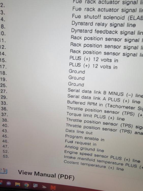
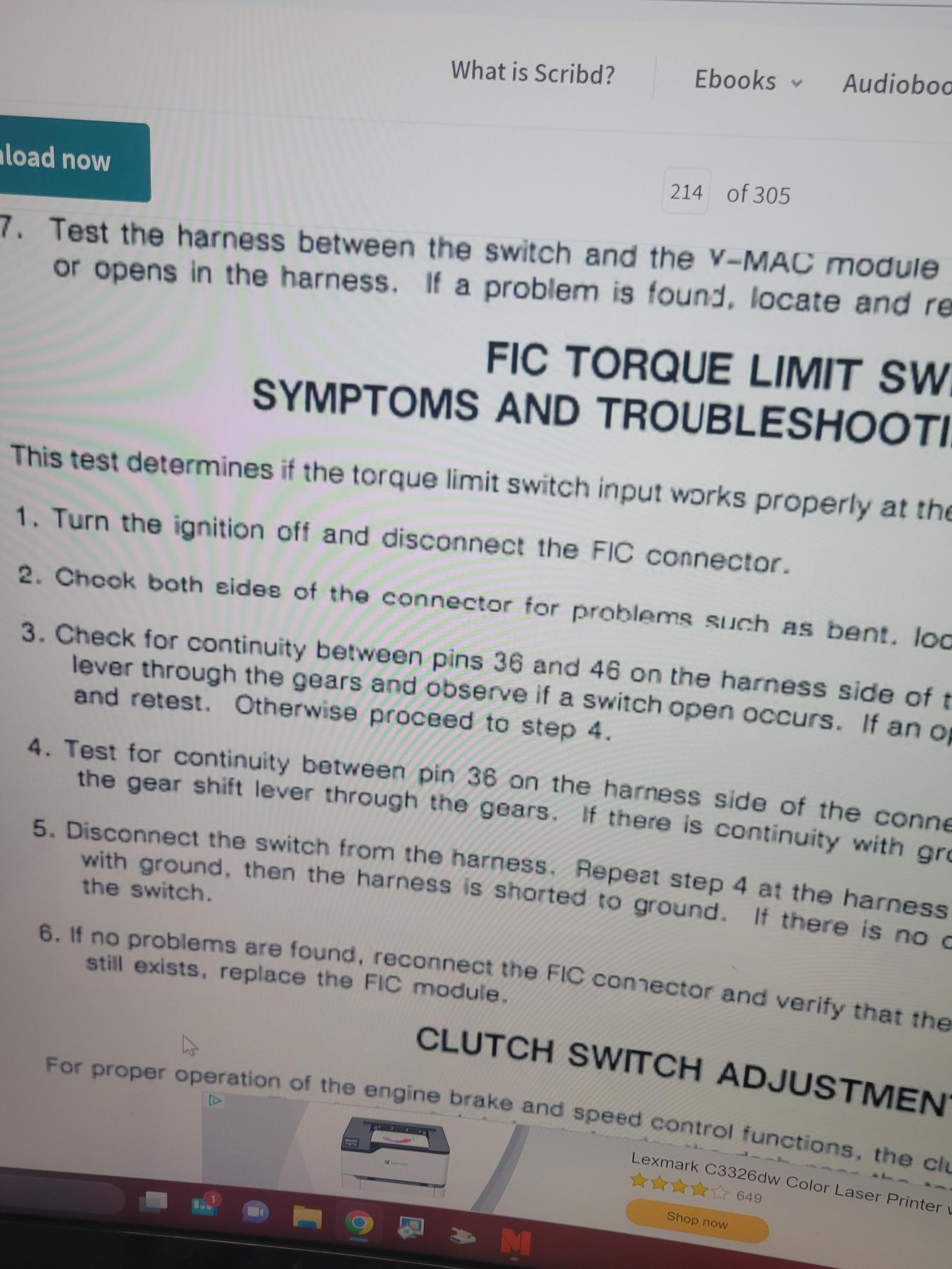
I tried connecting a light and ran wires to the switch same result. My understanding of the Torque limit switch, is a closed circuit pin 36 and 46 on the FIC means to apply the Torque limit feature. I completely agree with you about running the rack with no load is not ruling out possible issues on the fuel side. However I can tell you she was Definity wanting to run lol. With out taking the pump off and having it flow tested I don't know how to check fuel volume. Do you know of a test on the truck? lift pump psi to the injection pump was at 27 psi when I was on the last test drive. -
E7 low power help!
Dtech replied to Dtech's topic in Antique and Classic Mack Trucks General Discussion
Puppy Poster 94 Posted 14 hours ago Does it have the right injectors in it? Have you thermal gunned the exhaust ports? Dial indicator the rocker arms to check travel? Bent pushrods? Did you tie a light bulb between those two pins to simulate some resistance? Maybe pull that switch and apply air manually and see if that fixes the problem, although it might not be programmed in the ECU to begin with. If you got no boost and no smoke it's definitely pulling fuel, how does it pull in low range? Does it struggle at all? The Injector nozzle's are reman, But again if the rack is ran Manually the Injection pump has no problem pouring the fuel to the motor. I did check travel on the cam lobs its with in speck in the manual, did Not find bent push tubs when I checked the valve Adjustment, It run low in power all the time even low range. only builds 5 to 7 psi boost psi. Not sure about your question on applying air to the switch manually? There are no wires going to it. The switch is NC in low range and No in high range. Thanks for your input the more heads we have thinking about it the quicker I can figure it out. -
E7 low power help!
Dtech replied to Dtech's topic in Antique and Classic Mack Trucks General Discussion
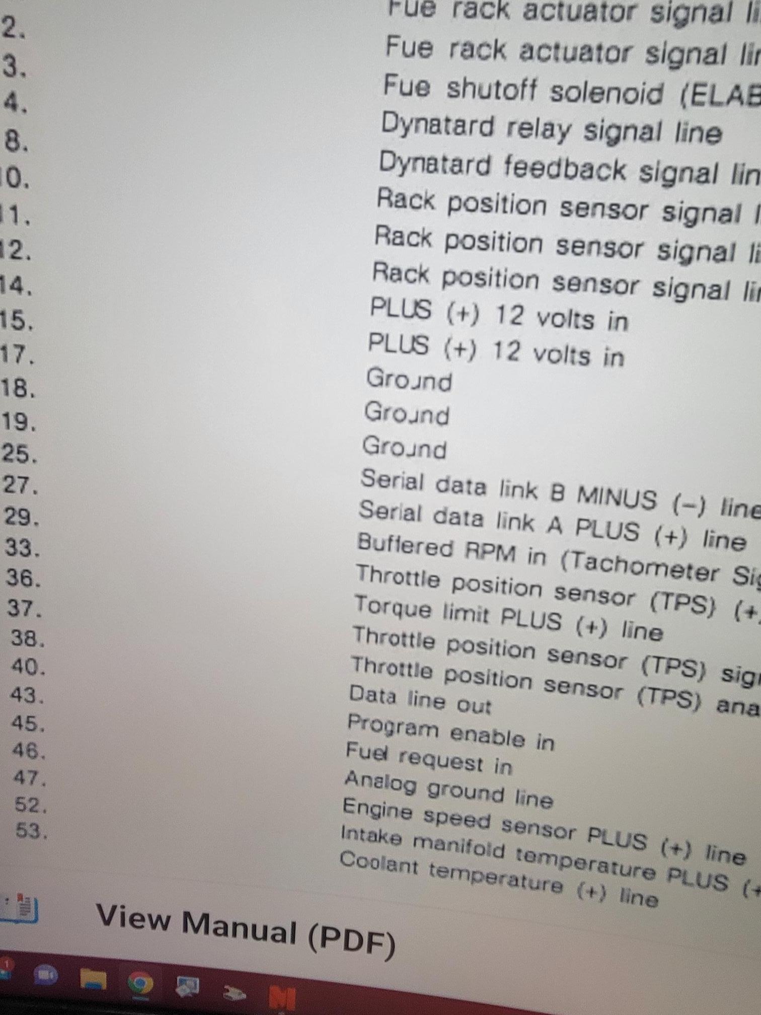
No black smoke, Only when I ran the pump rack manually. I did that test to prove the pump plungers fuel lift pump etc, are not the problem. This was done in the service bay not driven, but you could tell she was putting the fuel to it. When the truck is driven It will only build 5 to 7 psi of boost running down the road. No smoke engine feels like it is in the Torque limit derate. I checked the timing by the book and by using a J-37077 timing tool. Its a 1995 E7 ch613 The complete vin is 1M2AA13YXSW058895. I found a old Prolink 9000 on eBay so I can hopefully watch the Torque limit parameter? Now as far as the Torque limit derate switch, no wires going to the switch that I can find. The wire pinout calls for wire 36 at the FIC as the signal wire for Torque limit derate. That wire has voltage on it with the key switched on 4.7 v. The wire it should be connected to pin 46 at the FIC is a ground. My understanding of the circuit is that it is Normally closed during low range pin 36 to 46. No active or inactive codes, the Diesel laptop scanner I am using right now shows' me that TPS is 100% and load is 100% during the test drives. It will not display the Torque limit parameter so I have no Idea if it is programmed for it or if it is in the active derate state. However completing the circuit pin 36 to 46 makes no difference in power. -
E7 low power help!
Dtech replied to Dtech's topic in Antique and Classic Mack Trucks General Discussion
Yes I have checked for boost leaks, The black smoke is only when I was manually moving the Rack inside the fuel pump. Items I have checked so far Turbo, Intake, air filter, air compressor supply line, Air charge cooler, Fuel psi, exhaust restrictions, valve lash, Cam Timing, Injection timing, Tps, intake air temp sensor water temp sensor. The scanner shows it going to 100% load. I can only watch the following parameters oil psi, water temp, intake temp, tps, load, rpm, road speed, and voltage. Can anyone shine some light on the torque limit circuit for mac I, why would wire 36 be labeled positive and wire 46 be a ground? I also don't understand why the wires have voltage on them. -
E7 low power help!
Dtech replied to Dtech's topic in Antique and Classic Mack Trucks General Discussion
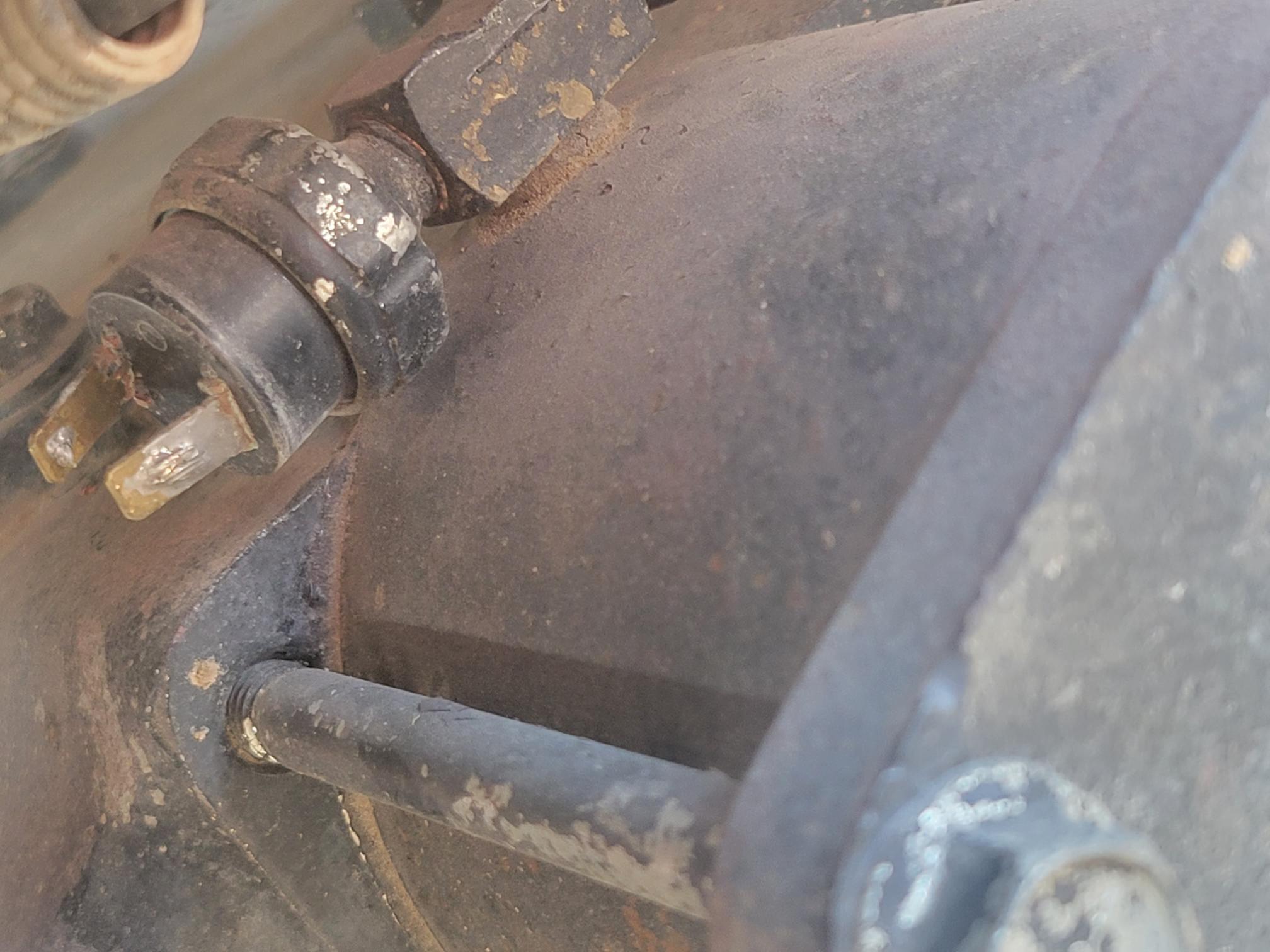
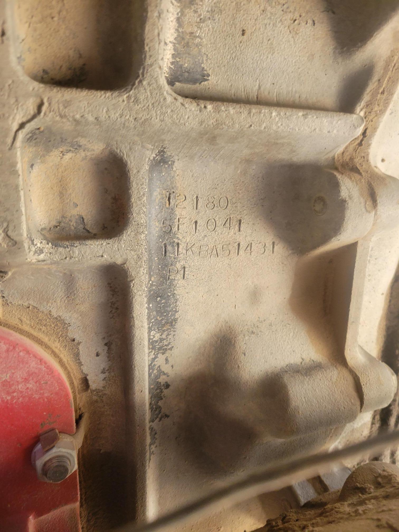
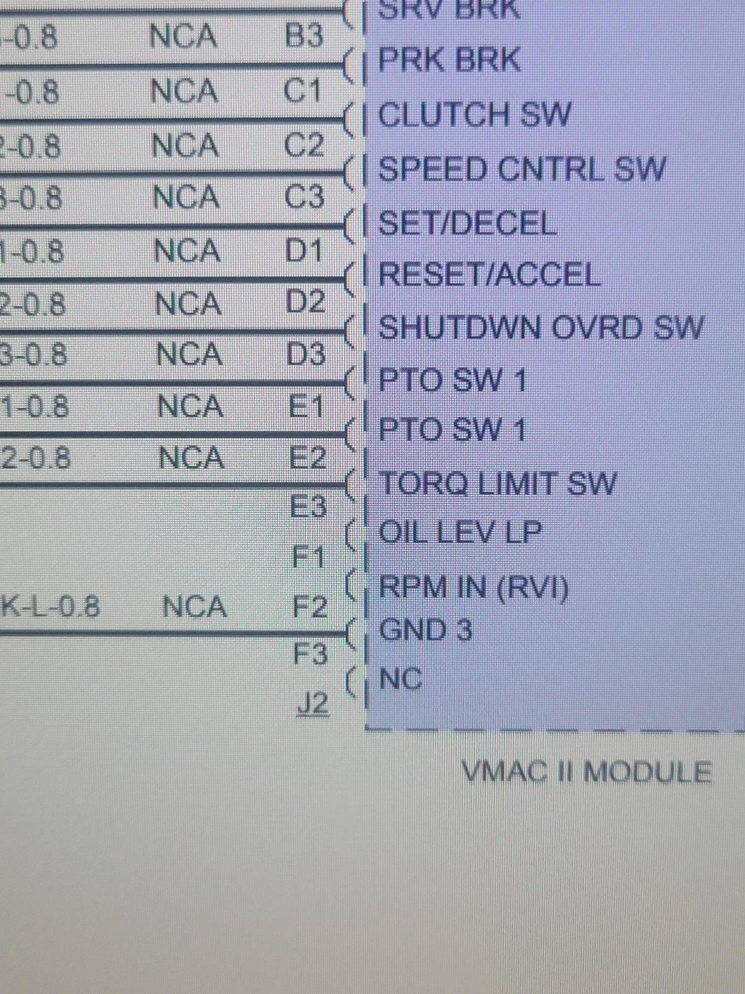
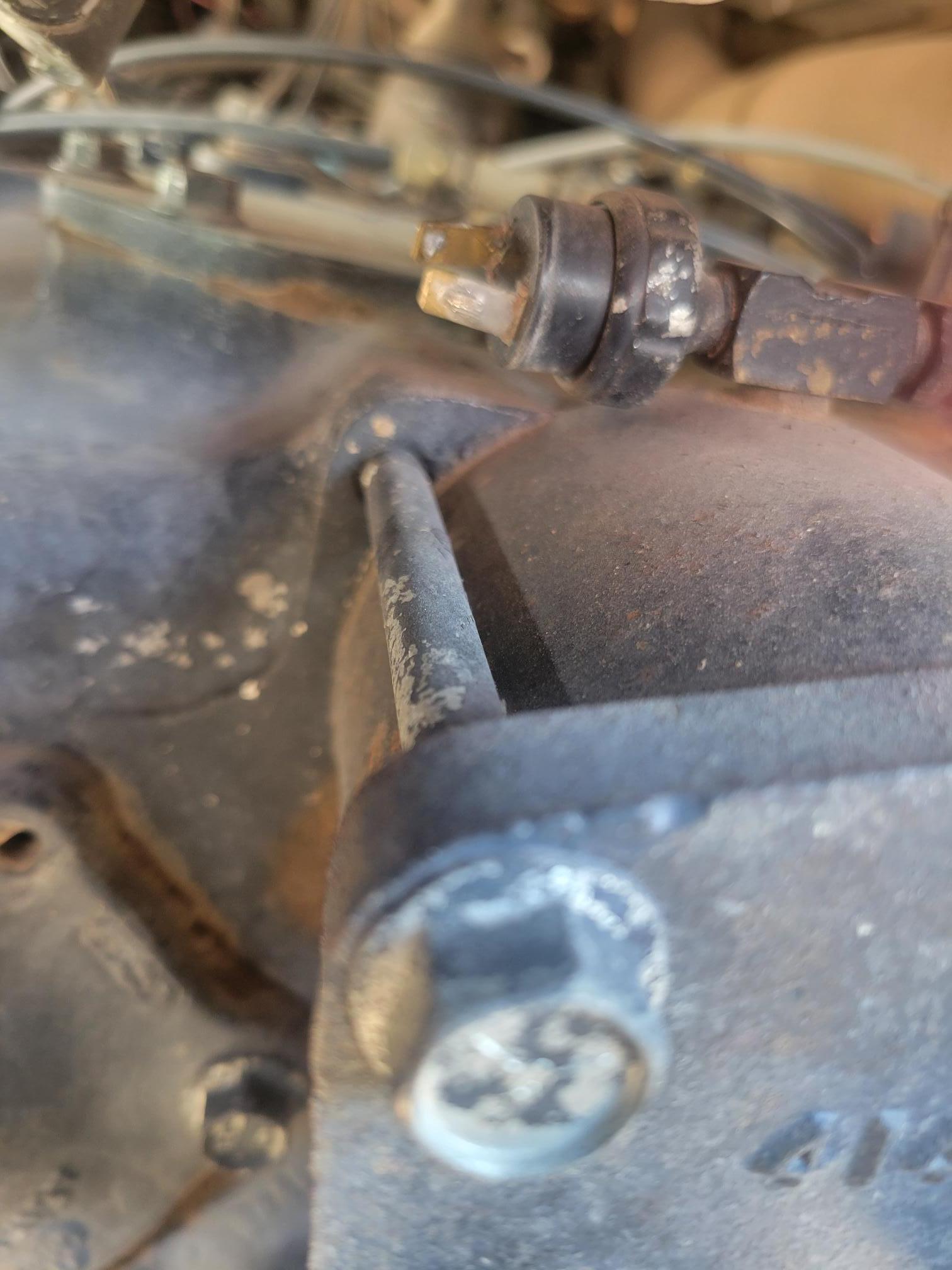
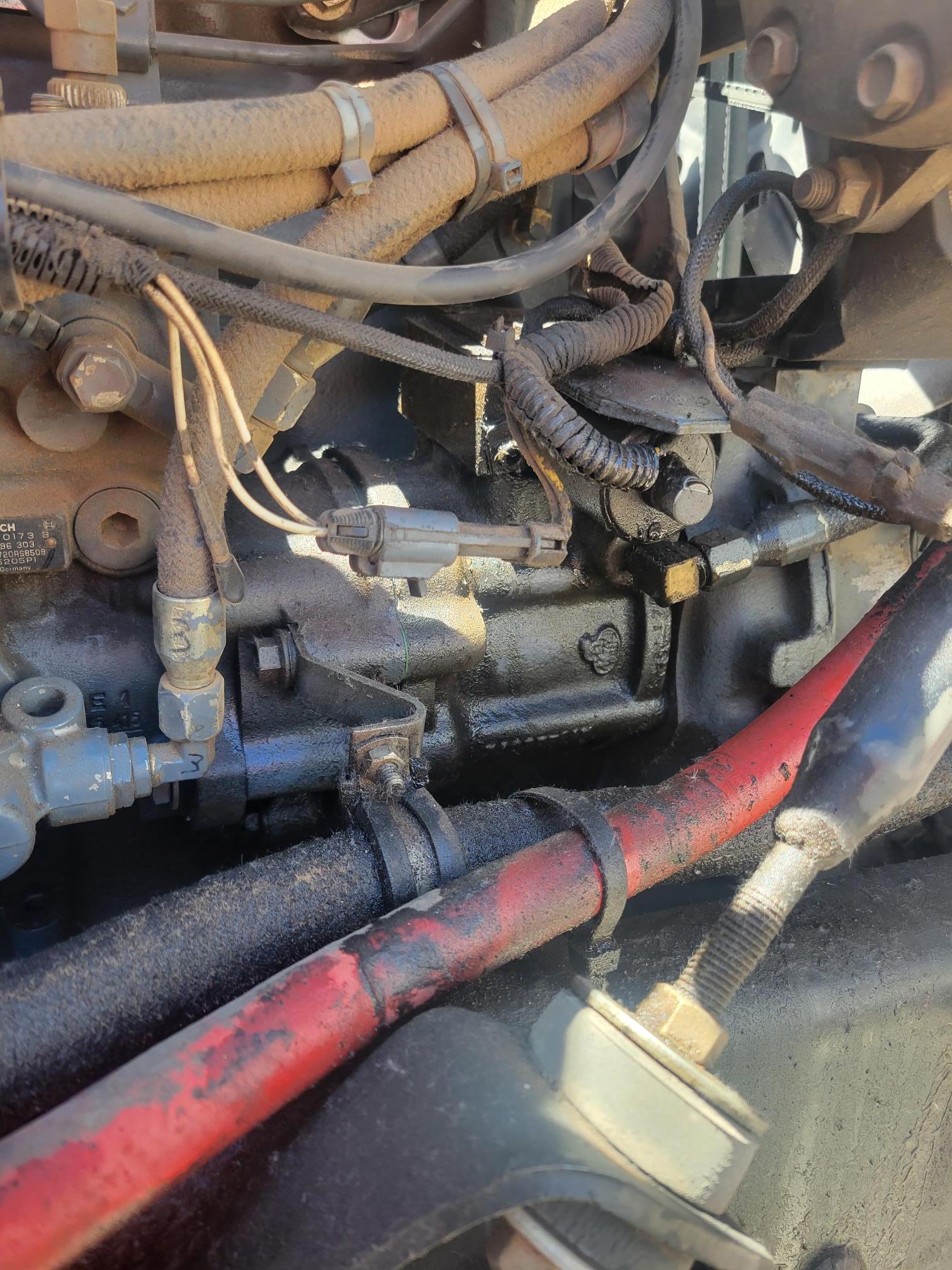
I have A t2180 for a Transmission, I do not have any active codes. This motor has low power just like it is at 50 % derate. The switch in the picture is what I believe Mack used as Torque limit switch. Do you know how the torque limit circuit works ? Does it ground wire 36 in low range? Why do I have voltage on that wire and 46? I have mac II software but can not find a adapter that will communicate so I have no Idea if it is in a Torque limit state. I cut wire 36 so no chance of a false input, still has no power! The story I was given is that it ran well before the out of Frame overhaul. However I talked to a driver yesterday that told me this truck has always been under powered? I took off the eclectic part of the Injection pump governor and ran the Rack my hand! She Definity rolled some smoke then so I feel the pump can produce power.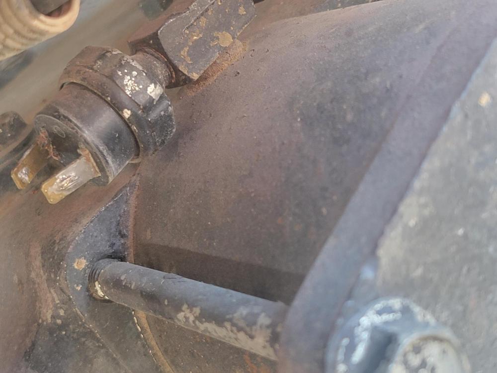

-
E7 low power help!
Dtech replied to Dtech's topic in Antique and Classic Mack Trucks General Discussion
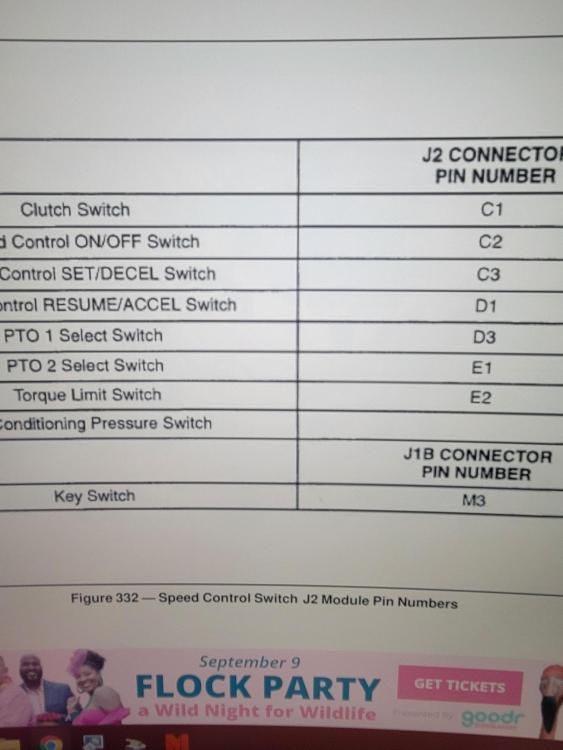
Ok I am needing some help here I have a mac I system not a mac II ! so the above picture is not correct. According to the manual I should have a connection between pin 46 and 36 on the FIC plug when in low Range for the torque limit switch I do not, and do not have it in High Range also. I do have 13v on pin 46, and 9.8v on pin 36. with the key on I have 13v on pin 46, and 36 with the key off? I wonder if I have a bad FIC? I am also confused on the pin out chart, it labels pin 36 as Torque limit Plus + line and pin 46 as analog ground line. Anyone have any insight on this circuit ? Thanks Jeremy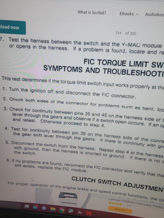
-
E7 low power help!
Dtech replied to Dtech's topic in Antique and Classic Mack Trucks General Discussion
Thanks yes, I found it and checked its clearance. I was wondering if the computer is in a torque derate? I found a sensor on high range that looks like it had wires on it. The customer did pull the Transmission so he might have not reconnected this sensor? I am asking about the wire E2 for the Torque limit switch is anyone familiar with this switch? It is possibly the switch in the picture above? I am going to check the wire at E2 to see if it is grounded.
-
E7 low power help!
Dtech replied to Dtech's topic in Antique and Classic Mack Trucks General Discussion
I am getting RPM on the scanner if I unplug the flywheel sensor I loose my tach and motor starts to run ruff. I also get a ruff white smoke if I unplug sensor on the injection pump. I noticed I have a sensor that seems to be missing wires on the back of the transmission. Did Mack have a torque derate if it was not in High Range? I think I ran into something along those lines before?
-
E7 low power help!
Dtech replied to Dtech's topic in Antique and Classic Mack Trucks General Discussion
yes you are correct on the info thanks! -
E7 low power help!
Dtech replied to Dtech's topic in Antique and Classic Mack Trucks General Discussion
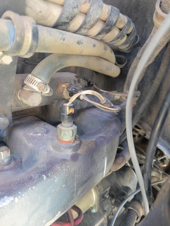
No I understand the importance of the valve adjustment. I apricate the help any Idea on the temp/boost sensor? Why would Mack and Pai list it as a dual sensor? I am lost on how this works only using two wires. When I ohm the sensor it has continuity between the two post, and it changes with temp. part # 20705960. Does anyone have a ecm wire diagram for the engine sensors? -
E7 low power help!
Dtech replied to Dtech's topic in Antique and Classic Mack Trucks General Discussion
Well I eating some humble pie this morning I made a mistake yesterday my dial indicator was hitting the Jake housing so I got a false reading. Its hard to see the timing marks and watch the indicator at the same time. So the cam Timing is correct at 27 deg's Mack dealer said the cam part # is a 454605142. According to the chart its on the money. This one has me stumped we crossed off intake leaks, exhaust restrictions, Turbo, valve lash, camshaft timing, injection pump Timing, and fuel psi. Even if they installed the wrong cam I don't believe it would be this low on hp. Its a complete dog! I looked at the injection pump rack Travel, it does not hang if I start it with out the computer controlling it will defiantly put the fuel to her. So it has the ability to run well. I don't understand why I can't find the intake psi sensor? Mack dealer said its sensor 20705960 boost/temp sensor. I am confused it is only a two wire sensor how can it have two circuits with only two wires? If I unplug it I get a active code for intake air temp. Nothing for boost. -
E7 low power help!
Dtech replied to Dtech's topic in Antique and Classic Mack Trucks General Discussion
Yes but I would also like to install my timing light and find out what exactly the timing is at now, and what it is going to at high rpm. I don't understand how he could have gotten in off? Does it not have marks on the two gears? 🤔 -
E7 low power help!
Dtech replied to Dtech's topic in Antique and Classic Mack Trucks General Discussion
Well I got the chance to check the valve adjustment and it was spot on. However I use the Camshaft timing check procedure in the book using #3 intake valve. I end up at 34 deg's The chart in the book said 27 deg's for cam part # 5205, 26 deg's #5142, 20 deg for part # 583, 583A. The book said I should be +- 3 deg's. Can anyone tell me off my engine ser# what cam part # I should have in this motor? Engine ser# 5F2052. The customer has no record of what was put in it! I could use some advice but I feel that the camshaft to crankshaft timing might be off? Also on my test drives the Jake brake does not seem to hold back well at all. However I am building very little intake psi 5 to 7 psi so its hard to judge it, but to me this also points to cam and crank timing being off. Thoughts -
E7 low power help!
Dtech replied to Dtech's topic in Antique and Classic Mack Trucks General Discussion
We will have a bay open soon so I can run the valve lash finally lol. I will check the plug with some back prob pins also. The timing advance solenoid has oil dripping from it. Would the ECM throw a code for Timing not changing? I guess I can put a timing light on it and watch what it does on the RPM curve. -
E7 low power help!
Dtech replied to Dtech's topic in Antique and Classic Mack Trucks General Discussion
Joey You said that the pins and come loose. Are you talking about inside the pump? or on the electric round connector? -
E7 low power help!
Dtech replied to Dtech's topic in Antique and Classic Mack Trucks General Discussion
I don't see anything like that on this one. I Have seen it before on older models, however this has electric wires going into the pump, no lines leaving the intake Manifold besides the air compressor air supply line. The only sensor is a two wire intake air temp sensor. I found a new pipe plug in a port that made me think he missed the sensor when rebuilding it. Some info on the truck Vin 1M2AA13YXSW058895. 1995 E7 -350hp engine ser# 5F2052.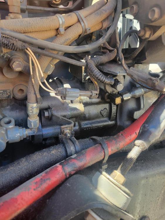


BMT Forum Logo
