


Ryanp
-
Posts
24 -
Joined
-
Last visited
Content Type
Profiles
Forums
Gallery
Events
Blogs
BMT Wiki
Collections
Store
Everything posted by Ryanp
-
2004 MR688 transmission output speed 4-1
Ryanp replied to Ryanp's topic in Electrical, Electronics and Lighting
Alright guys so I got a sensor from napa that he looked up for a 2004 mack truck. I told him I needed the thread in one with a pigtail not the bolt down one thats stubbed out at a 90. Got it in and hooked up to the "truck" speedo wires and everything seems to work. The trans is seeing what it needs to and the truck is seeing what it needs to. Psimple fix i guess. I dont think its supposed to be that way but it worked out. My other 2001 mr688 does not have that hole drilled/ tapped but there is a boss on the tailhousing for it. So to be clear for anyones future reference I am running two separate speed sensors in the allison trans tailhousing. Thanks guys the truck runs out pretty nice and is acutally smoother than the 2001 for some reason. Wouldnt expect that with a 20k front and 46 camelback! -
2004 MR688 transmission output speed 4-1
Ryanp replied to Ryanp's topic in Electrical, Electronics and Lighting
Well Ive gone a few ways with this this last week and I believe I'm ready to wrap it up. Just looking for so recommendations or so I hope. The output speed sensor has 2 wires. (Say A and The Allison reads off a 270-330 ohm sensor. (2 wires) The VECU has 2 wires to the "MPH Sensor" (vj2-11 and vj2-12 i believe) All this agrees with the drawings that i posted earlier and the Allison tech confirmed this. The problem is there is one output speed sensor, when I tried to tie them both onto the one sensor it messed with the signal to the TCM and did work for the VECU. So basically I can do one or the other but not both! Put the sensor to the TCM and it drives and shifts, but no speedo and limp mode with 4-1 code. Sensor to the VECU and it wont shift but the truck has power and speedo works. Throws a code on the trans for speed reading. My temporary solution was to put a second sensor to keep them both reading 300 ohms. TCM is hooked to the output sensor on the trans, VECU is hooked to another sensor that is dangling there. This seems to have solved it!! There is a second hole on this output housing with a threaded hole. I have a (mack?) sensor coming that has the old thread in and jamnut style mounting vs the slide in and clamp down one that was already in the other spot. Does this seem reasonable? Seems the TCM and VECU should be able to take readings off the same sensor by communicating between eachother but for some reason they arent? But then the wiring schematic shows them both to individual sensors? I dont have a part # for the threaded one coming, hoping it reads the right signal? Also I think the second hole only has 4 square tongs vs 24 or whatever the first sensor has. Any input on this? I may be getting into the redneck make it work to get by zone, but its time to get this truck out of the shop! -
2004 MR688 transmission output speed 4-1
Ryanp replied to Ryanp's topic in Electrical, Electronics and Lighting
Yesterday I replaced the signal wire from the vecu to the VSS. Now I can get the code to go away if I wiggle the wire in the vecu connector. Its not easy to say how to move it and it only goes away for a second or 2. Can I take the vecu apart to inspect the pins inside the box? I put dielectric grease on the connector and made sure every wire on my J2 was in tight and clean. Only thing I can think is one of the pins has cracked inside the vecu? My brother is pretty good at repairing circuit boards so that's who Id have look over that. Thanks for the help guys seem to be gaining on this thing. -
2004 MR688 transmission output speed 4-1
Ryanp replied to Ryanp's topic in Electrical, Electronics and Lighting
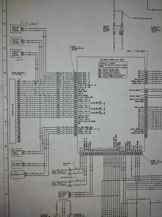
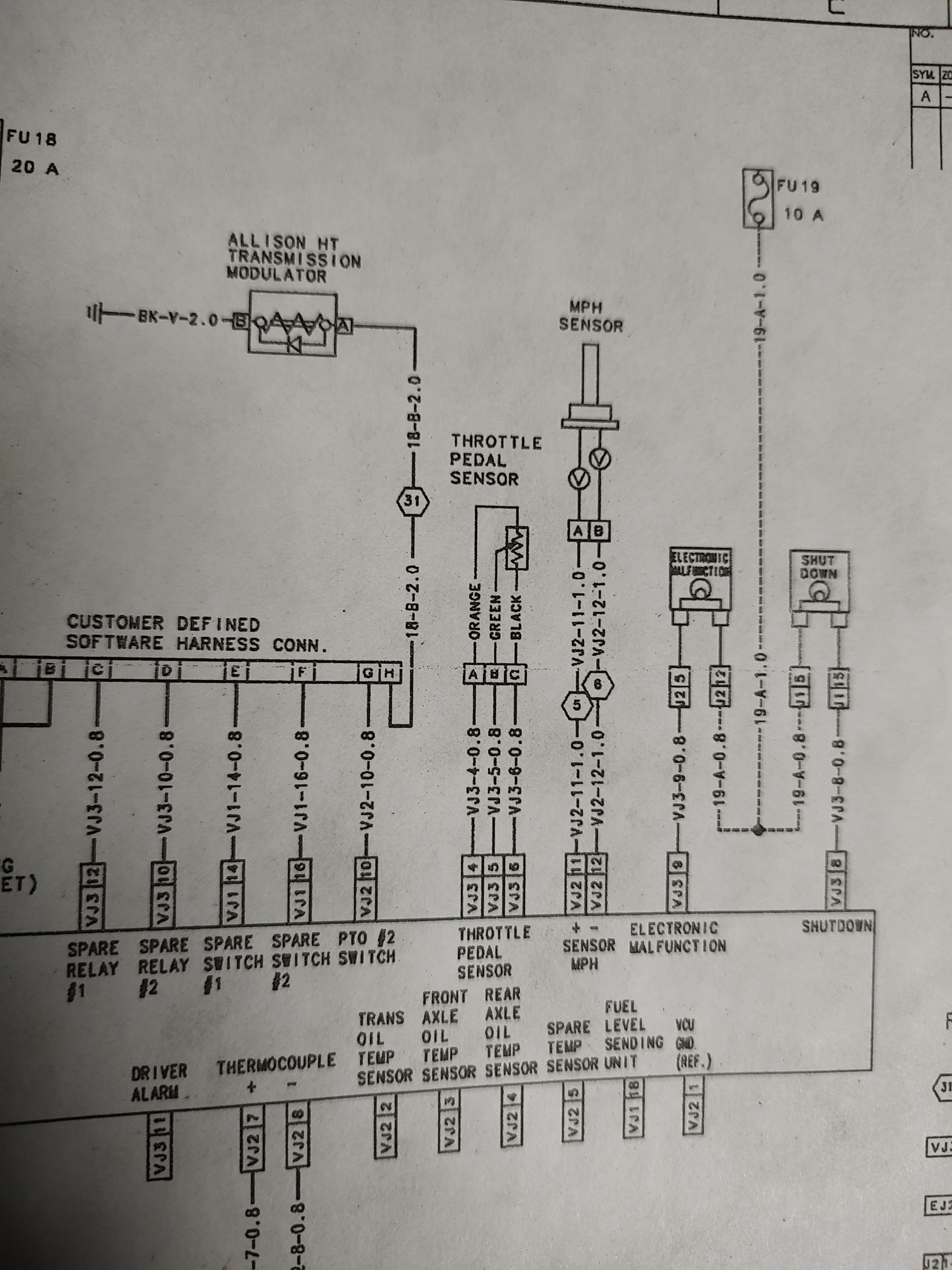
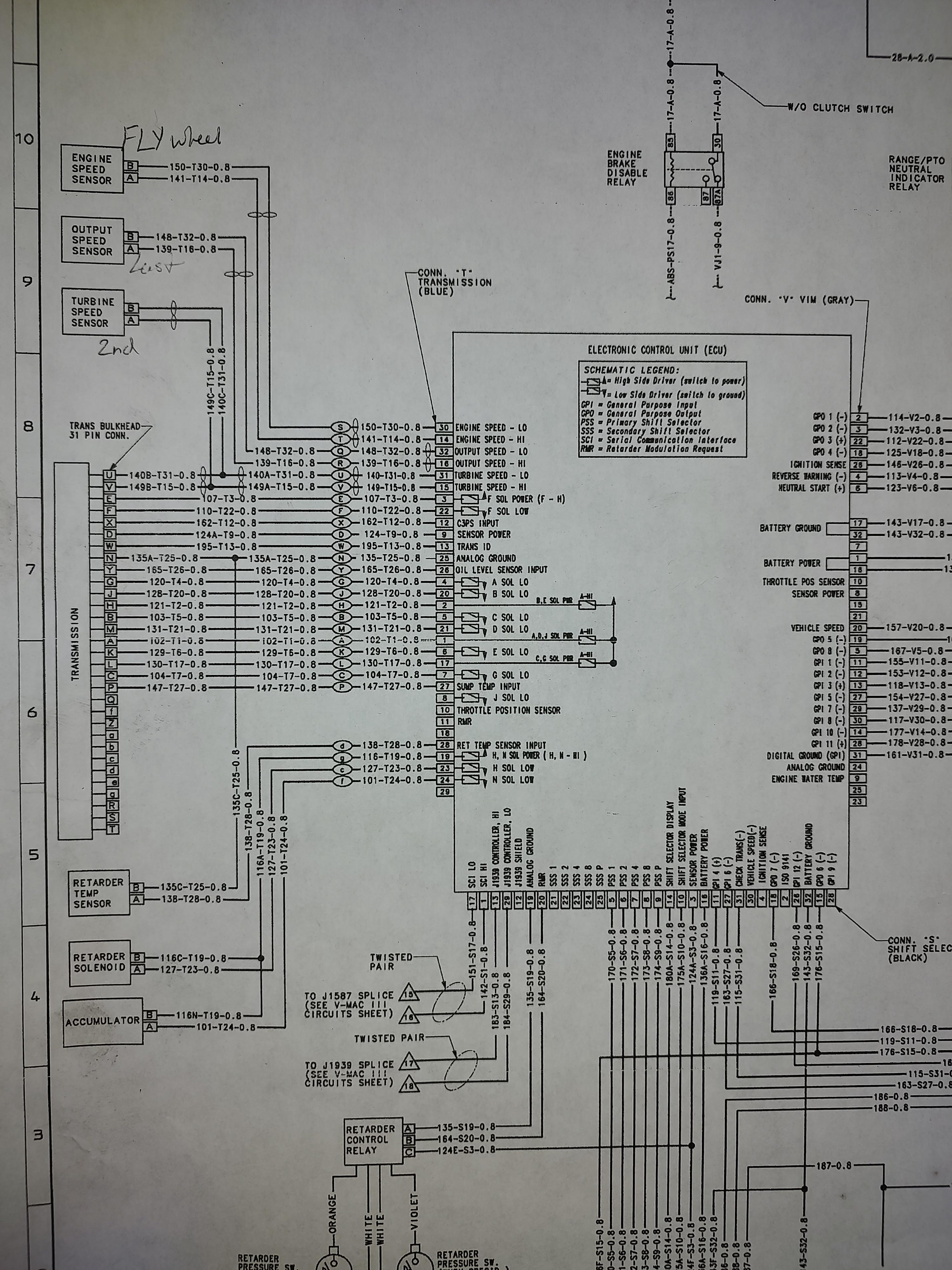
joey, Im having trouble understanding the wiring to this sensor I think. I found the schematic that shows the wire numbers and the connectors to the MPH sensor as you have been describing. I will attach it. That seems to be good I verified the bulkhead connector and now if I ohm pin 11 and 12 on J2 I get the correct 290-300 ohms off the sensor. I would say thats fine and good now right? Now the first post in this thread shows a different schematic that I thought was what I needed to be working with. The "ECM" in the diagram is the trans ECM that mounts right under the push button shifter. Then the "trans bulkhead" is the connector that goes down to the trans oil pan. Whats confusing to me is the "output speed sensor" in this diagram I would think is the "MPH sensor" from the other one? Each diagram only shows one set of wires to the sensor. Seems they usually make note of splices if there is one? Also I did find the PDF for test procedures for the VSS. That was very helpful. Thanks for all the help. Ryan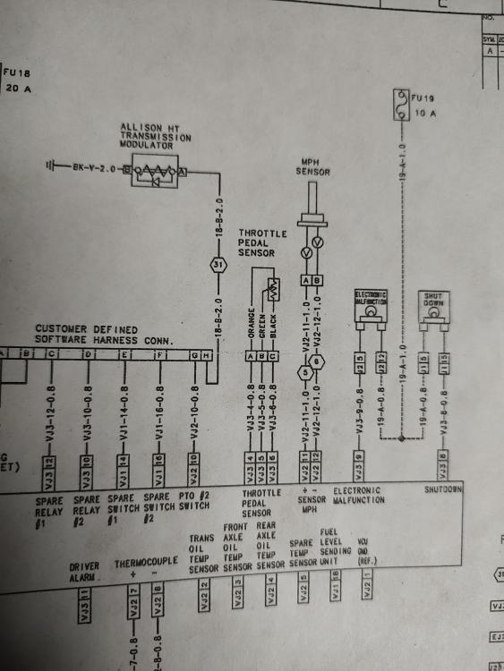

-
2004 MR688 transmission output speed 4-1
Ryanp replied to Ryanp's topic in Electrical, Electronics and Lighting
joey, Should I test the pins at the bulkhead connector or at the J-2 terminal of the vcm? The diagram I posted in the first picture shows what I'm looking at. Working with the output speed sensor now but there is also a "turbine speed" sensor on the side of the transmission, right in the side of the main case. -
2004 MR688 transmission output speed 4-1
Ryanp replied to Ryanp's topic in Electrical, Electronics and Lighting
joey mack, Yes it is an Allison auto. I believe the issue is low voltage on the sensor(s). I only have about 1.5 volts on the output speed sensor. Now if I unplug the bulkhead connector I get the 5v on the sensor. I have 5v at J-2 pin 11 and a good ground on 12. Is there a test for the turbine sensor also? Any leads onto good info would be very appreciated. Needing this truck up soon and Ive been too busy to dig into this more. Thanks, Ryan -
2004 MR688 transmission output speed 4-1
Ryanp replied to Ryanp's topic in Electrical, Electronics and Lighting
Joey Mack, Ive got 1.5 volts going to the sensor and 290 ohms across the sensor itself. What voltage should it be running at the sensor? Maybe I should check what kind of power I have on the other trans sensors, I didn't think of that. JoeH, The tube that the diagrams came in are addressed from a place called Pacesetter Enterprises. Allentown PA I looked online and cant seem to find it again. Also looking back through my emails for when it was ordered i cant find it. I will look tomorrow if there is anything on the sheets that say. -
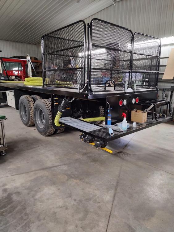
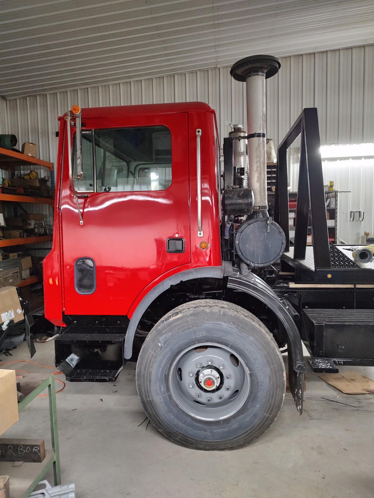
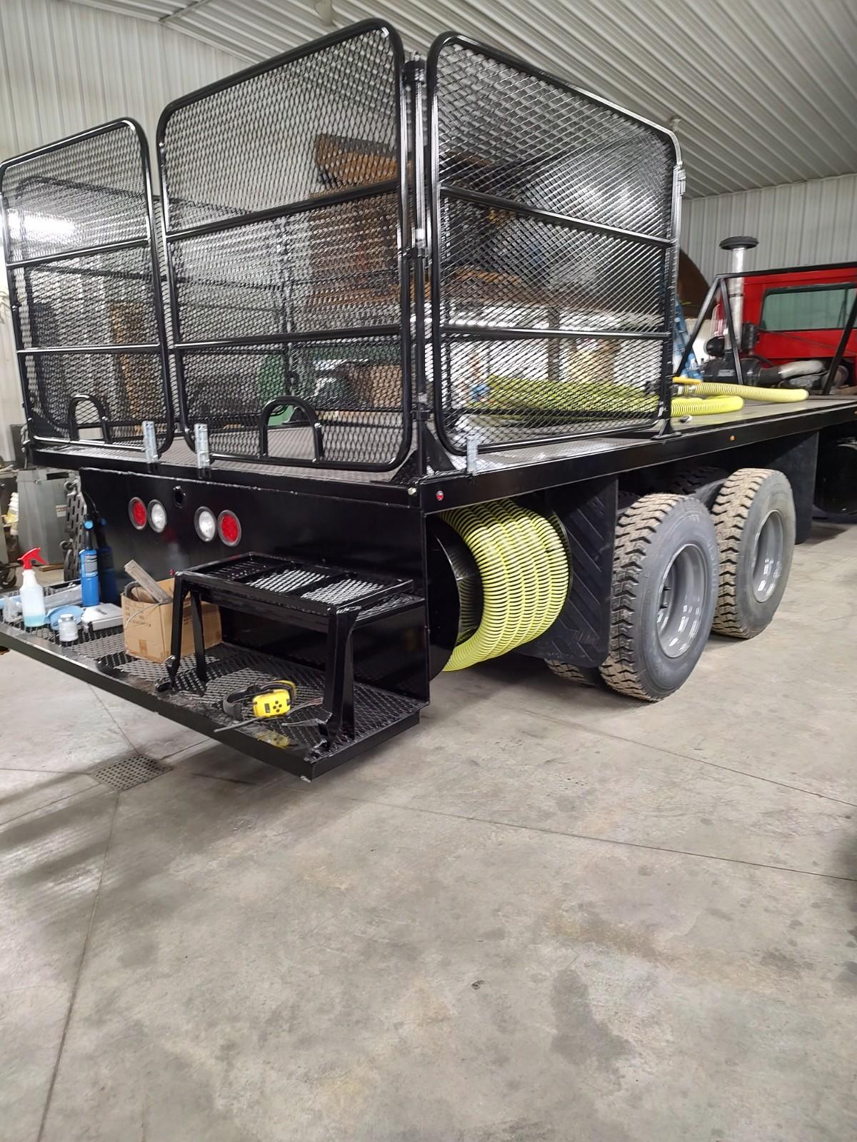
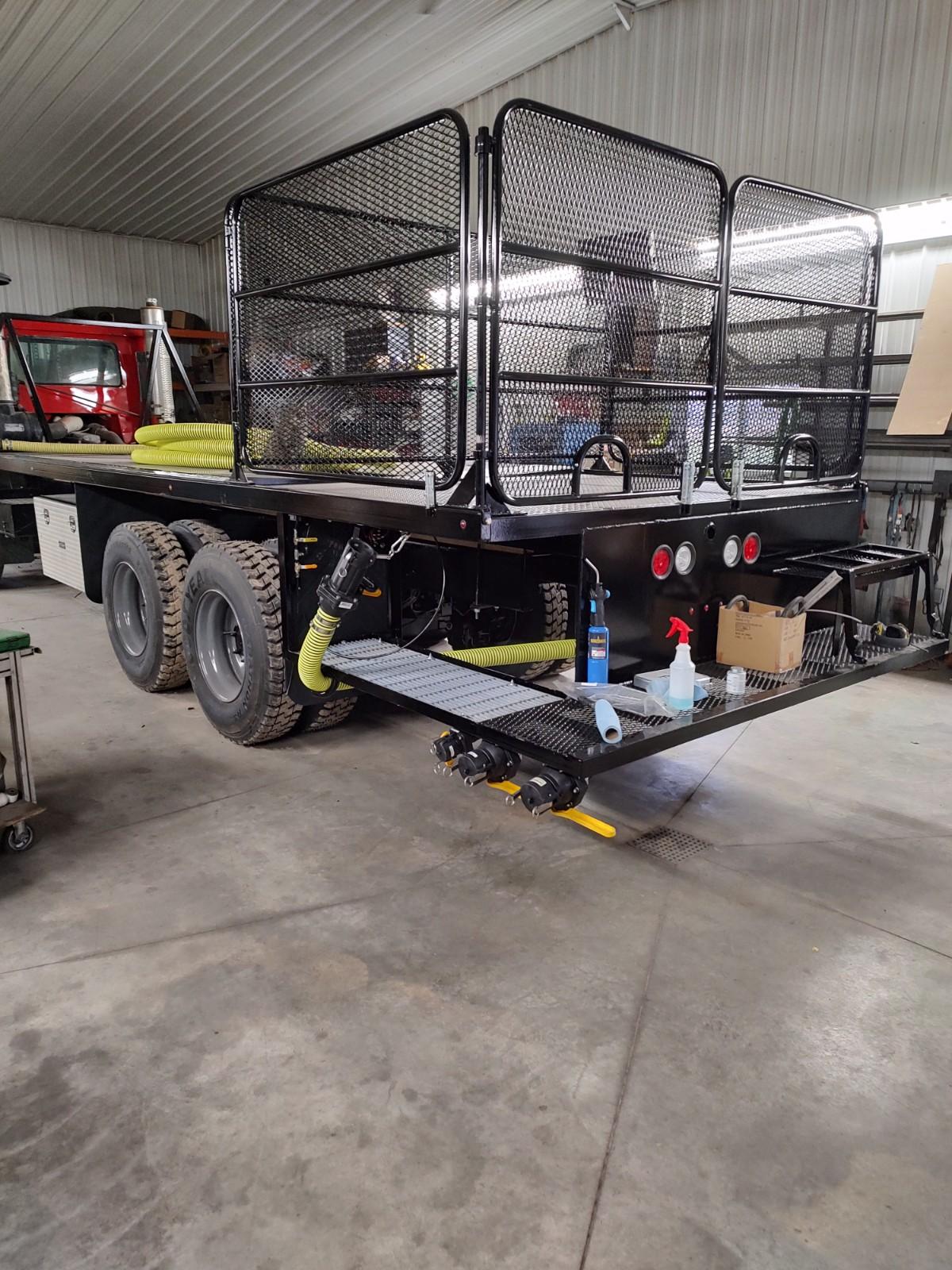
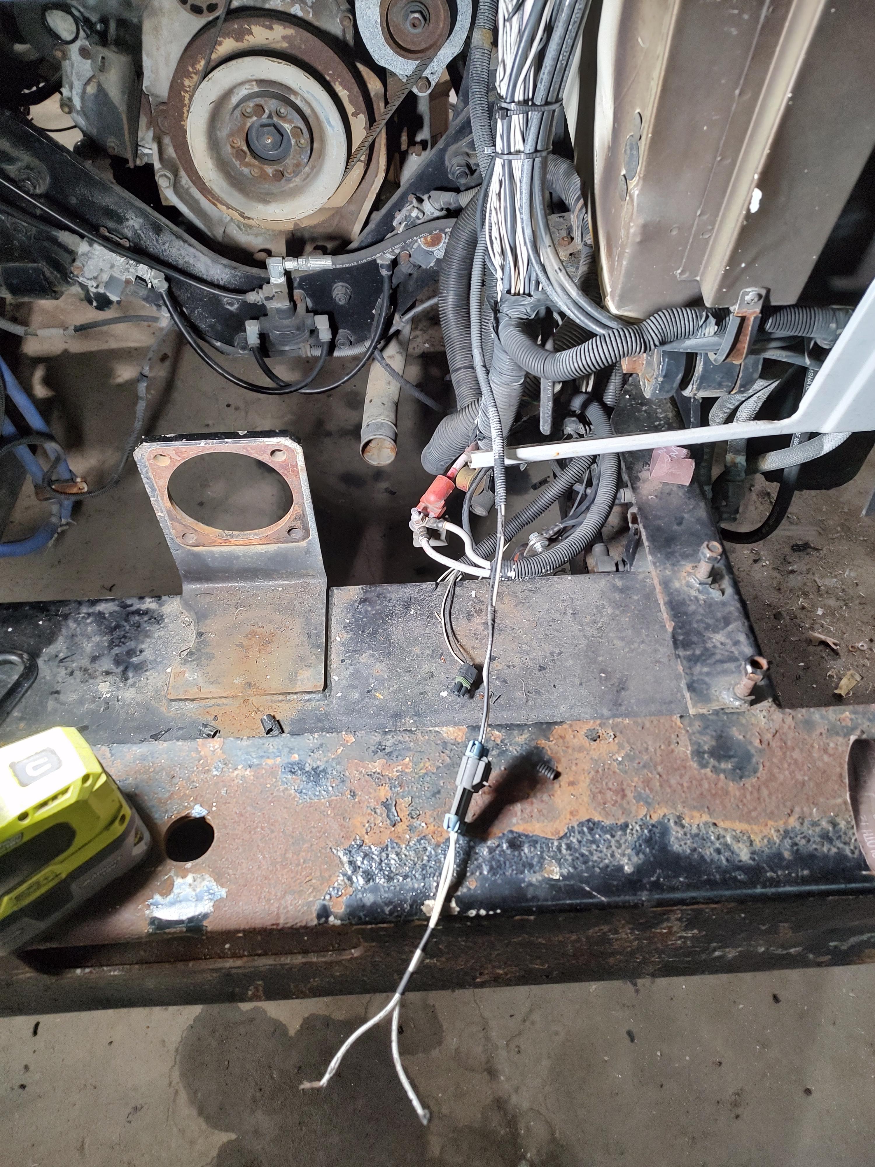
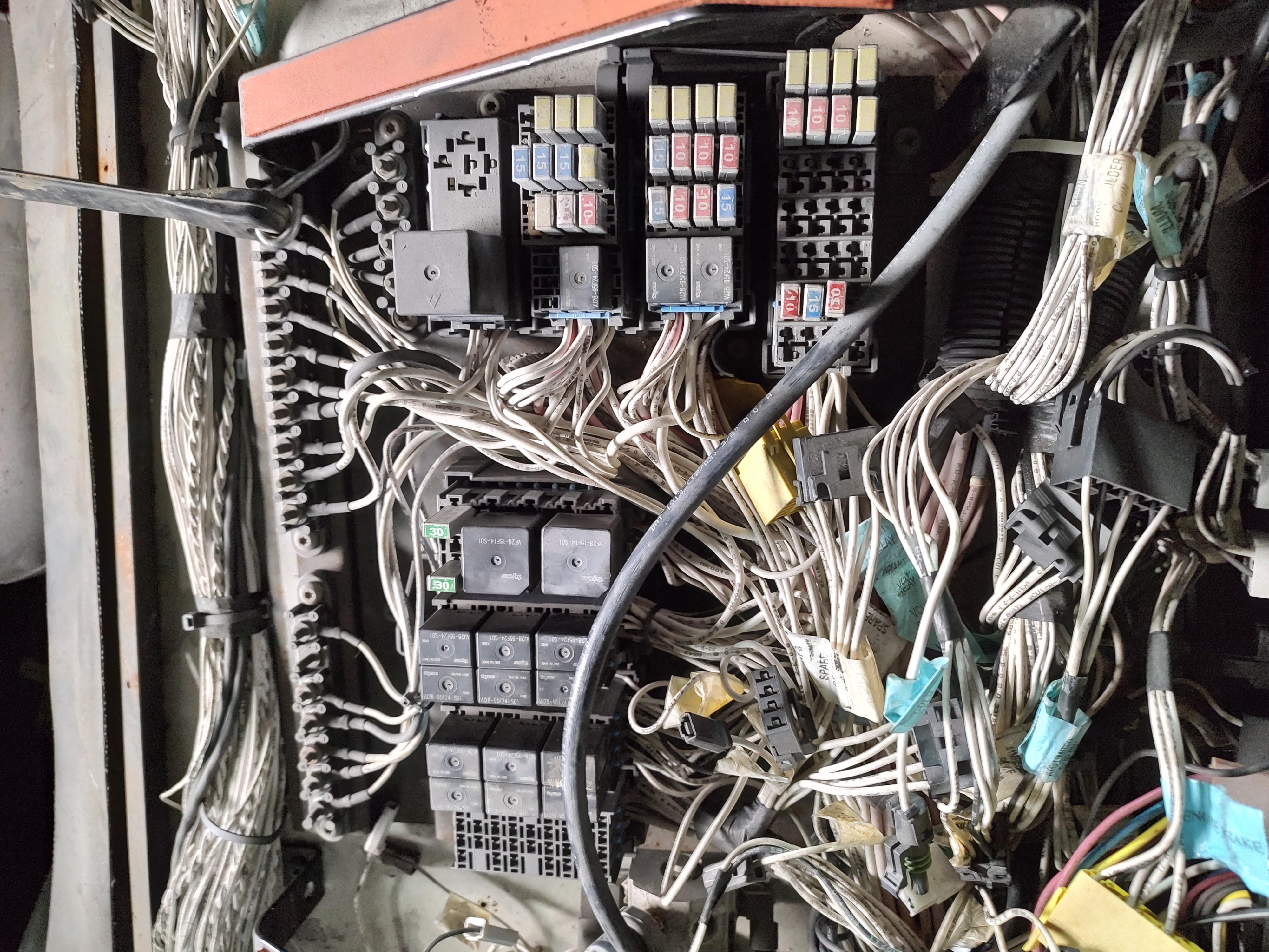
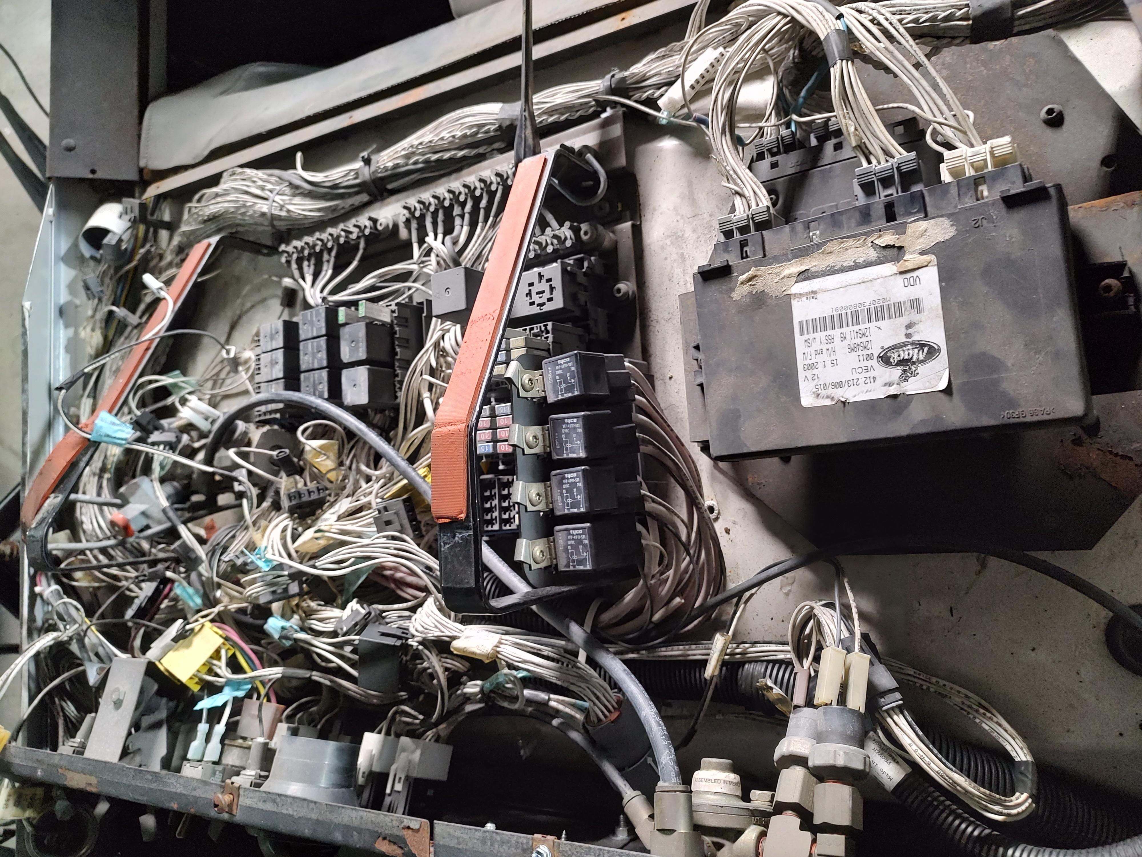
So Ive been working on this basket case MR 1/2 the winter and its time to finish the small things. Im down to 1 blink code I think. I have a 4-1 blink that indicates (transmission output) speed sensor problems. Trying to condense the situation as best I can.. Got the truck running but it wouldn't shift past 1st gear. (speedo worked) Figured out the harness from the trans controller to the output speed sensor was not connected because the wires that by the diagram were supposed to go to the sensor from the controller were stubbed out of the cab hinge connector and (factory?) heat shrink dead ended about 4" into the loom. So I went ahead and located the sensor wires, Not knowing where they actually went, (large harness going into the abyss by the oil filters.) cut them and ran my own new wires to the stubs that the diagram showed. Doing this made the truck shift properly but now the speedo doesn't work. So I figured the sensor wires must have originally ran up to the speedo in some round about way. So I spliced the wires back in so that now its the way it was, plus my new wires. Truck still shifts, but still no speedo. Speedo doesnt bother me that bad but it could be part of my 4-1 blink code? Looking for ideas and where to look next. I've got pretty good wiring diagrams but I'm not an expert. Picture of the diagram I'm looking at and some truck pictures for fun. Going to get tanks on it soon to be a sprayer tender.


-
Ok, so my latest on the truck is I got it driving this afternoon. I took out the trans sensors and cleaned/ inspected them. Looked good so back in they went. Took my blue connector off the trans ECM as per my schematic, jumped the sensor plugs and tested continuity at the ecm pins to see if It made a loop. Engine speed sensor and turbine sensor wires tested out good. Output sensor failed loop test. Messed around for a while and found the problem was between the hinge point connection and the sensor plug. Here's the weird part- I rolled back the loom at the hinge point connection, and where my wires were supposed to be pinned in at they were pinned in but only ran 4" and had what looked like factory sealed wire butt ends? Schematic said that the wires didn't run to anything special from there just back to the sensor so I ran a new set of twisted wires and plugged it all back in and it tested right and passed the road test. My question is where did the wires go that were leading from the sensor forward in the harness?? Possibly to the speedometer because that's not working now. Not sure if it was before or not. Current trans codes are 2314 and 2511 Still have a 1-4 and 4-1 on the blink codes. I haven't tried resetting the trans codes yet and I'm not sure how to on the blink codes? Thanks for all the help, it was fun driving down the road before dark even if it was 10 degrees out.
-
Well I put another 7 gallons in so I was way lower than I thought I was. After that it shifted into gear properly and all seemed well. Decided to take it for a lap around the shop and when its about ready to shift into second gear the indicator goes from 5 (normal) to 1. Clicking the up and down arrows didn't change anything. Then when I got it back to the shop to pull in I had to shut it off and disconnected the batteries because the shifter wouldn't go to neutral. Upon restart it will do forward and reverse like normal but if I drive it far enough for it to want to shift I will get stuck in 1st again. Its possible I have a bad sensor or 2, a couple of bad wires, or even the wires hooked to the wrong sensors on the trans. I've looked online and haven't turned up a good picture showing what sensor does what. I believe there are 3 on the passenger side and then the speed sensor on the output housing. I do have schematics with wire numbers saying what sensors they go to but they don't show the locations of the sensors. Also I'm still getting the 2314 code for the secondary shift selector. All my other codes cleared out other than this. Why would that be? There was a 4-1 blink code for the speed sensor but I think it went away. Thanks, Ryan
-
Well I thought I had the fluid close but it sounds like I'm only half way there. Thanks for clearing up the secondary controls thing. I will grab another pail at napa and see what goes on.
-
Hello everyone, I have a 2004 MR688 that I just got running this week. It has sat for probably 4 years, in the sun I might add. It has an Allison HD4560P transmission that is spitting out a bunch of codes and refuses to go into gear. Before I got it up and running I drained the oil. Probably only had 2 gallons in it. Then changed the filters. I believe I put about 4 gallons of fluid in it so far and I haven't checked yet to see how close it is but it shouldn't be too far off. Anyway the codes on it are 1412-oil level sensor failed low 2314-secondary shift selector fault 3312-sump oil temp sensor failed low 4522-G curcuit solenoid open 5587-oncoming c3ps test N1 to reverse and possibly 4523- solenoid H I see two of them might go away if I top it off more but I was wondering if there is a way to test the harness to diagnose these things. The harness is baked and cracked laying across the trans so that's highly suspect. Thanks
-
MR 688 electrical trouble shooting. No crank
Ryanp replied to Ryanp's topic in Electrical, Electronics and Lighting
Well everyone has been a lot of help. Yesterday I finished getting the EUPs freed up. They got progressively rustier as I got toward the rear or the engine. I guess that's normal with the exhaust. Got those back on and quick bled the injectors at the head. It started up and sputtered for about 3 seconds then took right off and idled normal. Gave it a minute then bumped it a little bit with the throttle and it seems to run pretty well. No gray or blue or black smoke. Runs right out. Thats a relief. I was beginning to wonder if I bought a big boat anchor. Now I'm on to the small things. I will be going through the air breaks and see how the transmission treats me. Hopefully easier than the engine lol. I don't want to have to learn too much about the transmission also. Thanks again for the help and resources! Ill start a build thread on the flatbed and what not when I get the welder out. -
MR 688 electrical trouble shooting. No crank
Ryanp replied to Ryanp's topic in Electrical, Electronics and Lighting
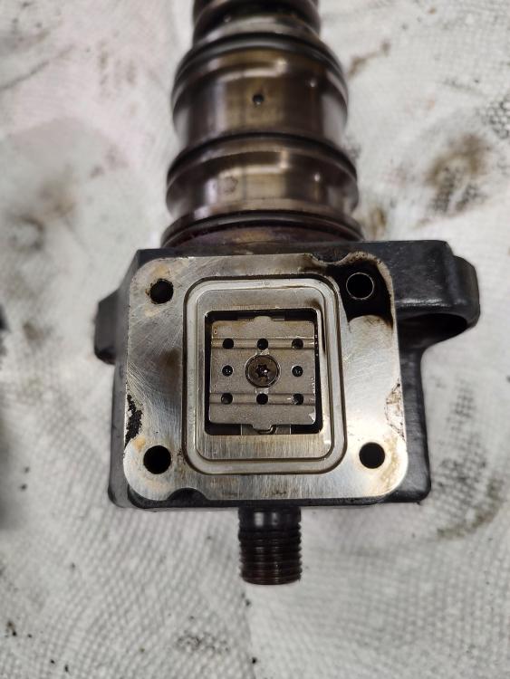
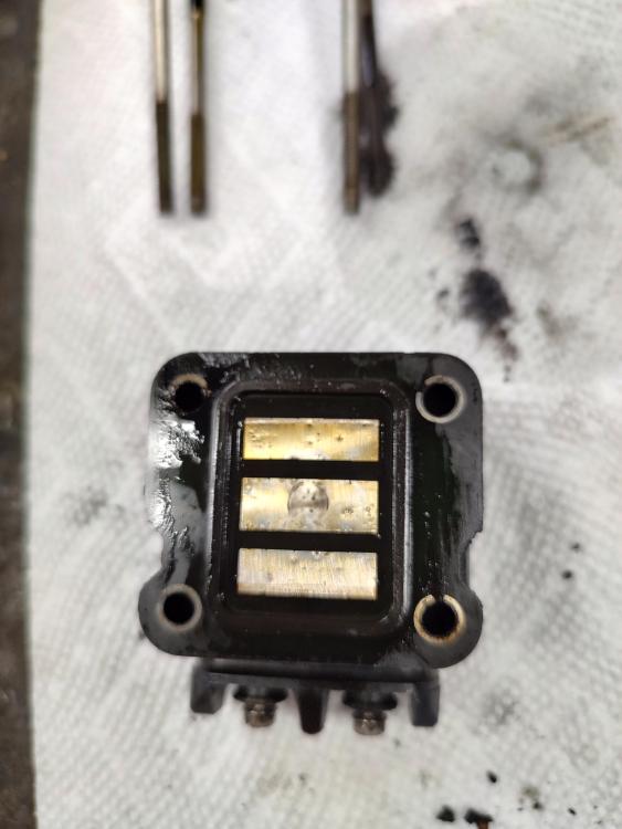
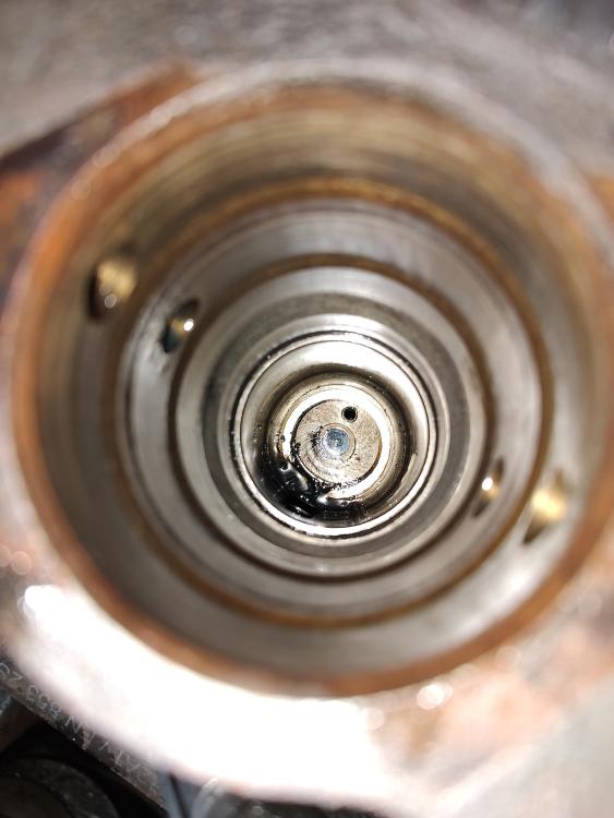
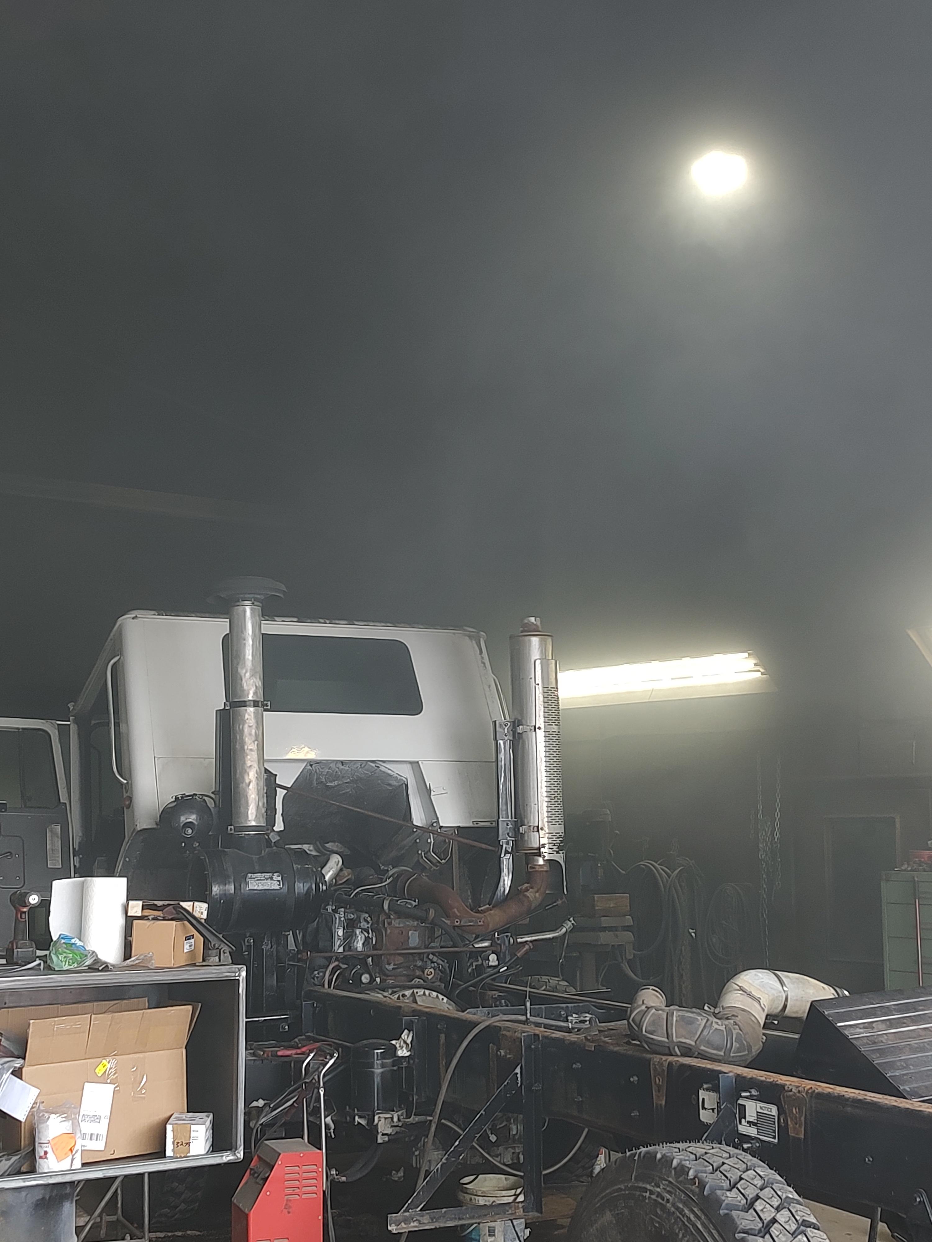
Well kind of made some progress today. Ran through the valves and they were all pretty close. A few were maybe 3-4 thou off. Ran It again, basically the same. Ive got probably 3 cylinders firing. This afternoon we fired it up and I shorted some of the EUPs as it was stuttering and trying to run. We thought it would show us what injectors were firing and what ones were not. Shorted cylinder 1 and it shut off immediately. #2 no change, #3 shut it off again immediately. Cant remember what the rest did but I plan to take the 5 that I haven't had off yet to verify the little parts inside move. Probably let them soak and get freed up? Not sure how sensitive the EUPs are but I've been keeping things clean inside. Got #2 off and sure enough that little square inside is froze up. Currently running on 3 ish and fills the shop in thick black smoke in about 2 minutes. I read that these things can get stuck open is that right? Or am I more likely looking at a set of injectors? Thank you all for the help, Its been great to have things to try. Learned a lot more about Mack engines and controls than I probably care to Lol.
-
MR 688 electrical trouble shooting. No crank
Ryanp replied to Ryanp's topic in Electrical, Electronics and Lighting
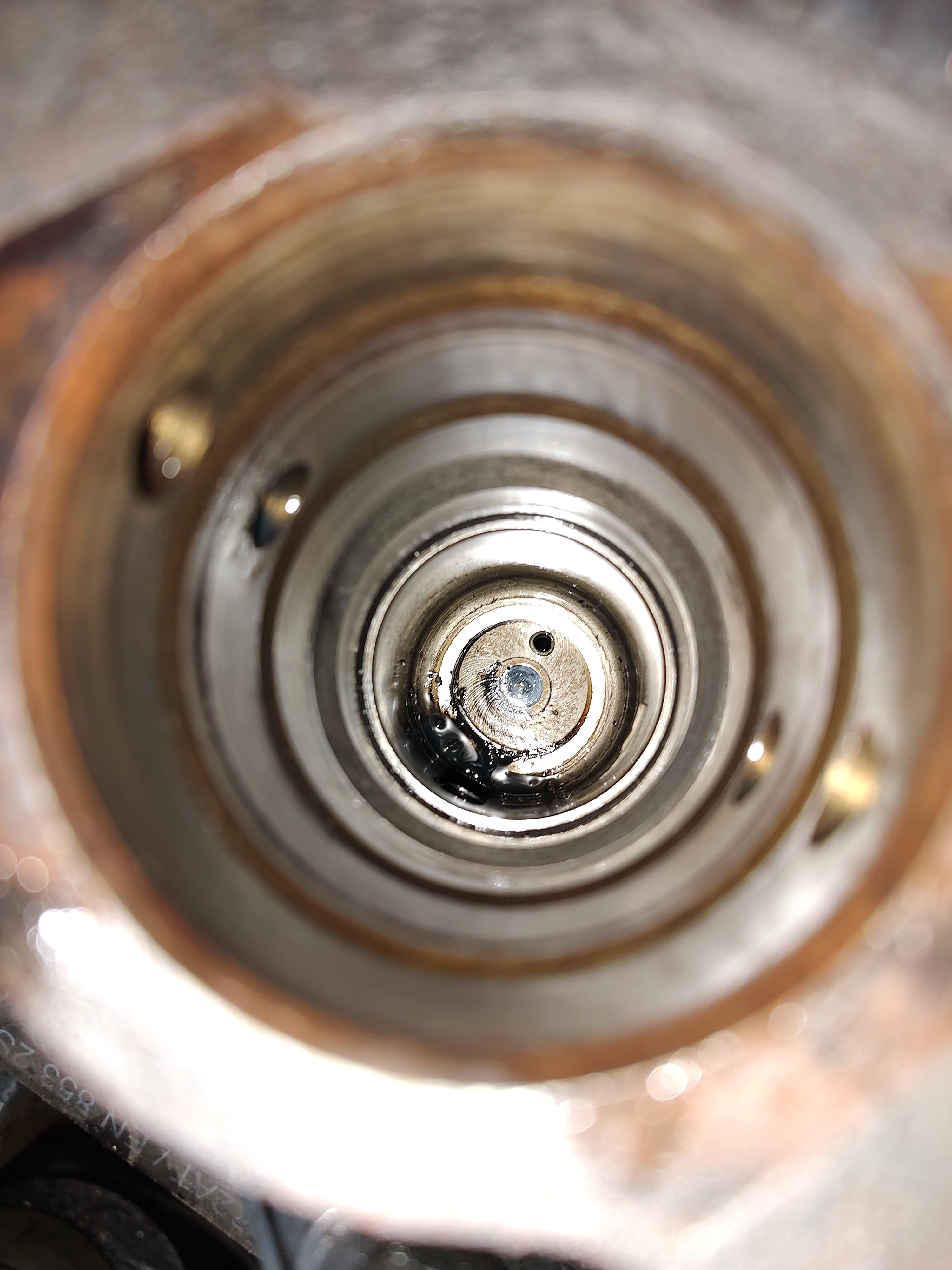
All right the grounds and power wires have all been cleaned up. I have a wire wheel on a cordless drill that is great for shining those things up. Frame ground and engine grounds are wire wheeled up and tight. Tested continuity on the wires from the timing sensor and flywheel sensor back to the eecu and they seem to work. Both (4) wires seemed happy. Batteries hooked back up and it seems to be mostly happy. 9-2 went away, 6-3 went way, 3-4 went away. The only codes that are still on seem to be the 1-4 and 4-1. Nothing that would keep it from starting is it? Now we've been bleeding the injectors at the head and I understand these are difficult to bleed but I feel like were missing something. I can get one cylinder firing and sometimes two will grab but it just doesn't want to take off. Its got so I can let off the starter and It will chug along for a good 10 seconds maybe but it doesn't keep running. Mostly a decent amount of grey/white smoke out the stack, seems when the other 2 cylinders fire we get a good puff of black. We can get 5 of the lines to bleed good at the head, the 6th seems a bit set up and we didn't want to twist it off. Pulled one of the EUPs to see what I could see and it looked pretty happy. Nothing dirty really, thought I might see rust from it sitting before I got it. Pics attached. I did manage to get the dirt/ oil out of the bore before I put the EUP back in. I am considering my issues now might be injector related? This truck did sit for probably 5 years or so without being ran. What issues could that cause on an engine like this. Haven't pulled any injectors yet, I understand they have issues with the holders in the head or something? Also I will have to download that 8-211 manual to my laptop! Thanks for the link, looks like there should be a ton of info in it.
-
MR 688 electrical trouble shooting. No crank
Ryanp replied to Ryanp's topic in Electrical, Electronics and Lighting
Thanks jojo, I will look into that harness further. Mine is definitely dry rotted and sun baked near the flywheel housing. We had 4 injectors bled good, just the front two giving trouble. I will give those last 2 a yank in the morning and get them done. -
MR 688 electrical trouble shooting. No crank
Ryanp replied to Ryanp's topic in Electrical, Electronics and Lighting
Well kind of made some progress the last 2 days on the truck. Got the fluids topped off and double checked a lot of the sensors and what not. Ive got the batteries pretty well charged up it seems to be rolling over decently quick. Still cant get the thing to fire off good. Im thinking there is a fueling issue? We've got 12v on the eecu. My codes are cleared up from what they were. There was a 9-2 and a 6-3 but I'm back down to the 4-1 and 1-4 now. Also there is a 3-4 that seems to be consistent. I think the 3-4 is to do with the sensor on the timing cover that tells engine speed or cam position? This sensor was missing when i got the truck so I got a new one for it. Now ive read that there are shims to get the sensor the correct distance from the gear? I do not have any shims on it. Wondering if this would affect starting/ running because the eecu might not know the engine position? We bled the injectors out pretty decent, 1 or 2 of them towards the front of the engine didn't want to bleed,(nothing came out, air or fuel) they would bleed fuel from the bottom of the lines but not at the top. We didn't try too hard to get the lines loose because we were afraid of twisting or hurting the lines. The nuts were backed out decent but the line was froze in the head must be. Right now it rolls over good and it sounds like one cylinder may be trying to fire. Getting white smoke out the stack and short black puffs I attribute to the one good cylinder. Hit it with ether and it will take off but only as long it has ether. Tach comes up to rpm so i'm thinking the sensor on the front is working? I am wondering if there is a way to test the coils on the fuel lines or if I need to be looking deeper into the block at the pump/cam set up? Could the timing be off some how? Also I dont think I've completely ruled out the electronics possibly pulling voltage down to 9-10v range when cranking. 3 new batteries and a good jump box. The draw seems like a lot. -
MR 688 electrical trouble shooting. No crank
Ryanp replied to Ryanp's topic in Electrical, Electronics and Lighting
JoeH, I did fanangle the wire terminals so they get a good grip on the relay. Seems to be pretty secure now. I believe I have the breakers/ relays/ fuses in correct order to get it going? There are still some missing but I robbed them from spots like the heated mirrors for now. Is there a test procedure to double check power on the eecu? I do have 12v at the CB-40 and I believe I stuck a 20A in there for now. I had one battery on to test things out and get the starter to engage. I do have 2 more that will get tied in before I plan on starting it. Blink codes are 2-3, 4-1, and 1-4. Trans codes are d1-2314, d2-3312, d3-1412, d4-4513, and d5-4512. When I looked up the trans codes off a PDF I found online there were a few that weren't listed?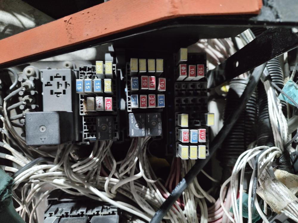
-
MR 688 electrical trouble shooting. No crank
Ryanp replied to Ryanp's topic in Electrical, Electronics and Lighting
Well everyone has been a lot of help. Today we made some more progress. The "clean power" was sure enough just hanging out not plugged into anything. I had also assumed it was for the garbage PTO pump or what not. Wires were numbered exactly as JoeH had shown in his schematic. Trans powered up and I read some codes off it. I left my paper at the shop and cant remember the codes. The blink codes I also have wrote down at the shop. 4-1,1-4, and 2-3 I think. My research told me ambient air temp, speed sensor, and coolant temp if i remember right. I will get those codes tonight. This still did not fix my no crank issue Ive been working on. I have been mostly working alone and this afternoon, my uncle got in the drivers seat and was messing with the key when I was bumping the relays and fuses. The neutral start relay had loose connections that once the key was turned and I bumped the relay it rolled over. Thank goodness. Still need to figure out my codes and get a few other things tied up but hopefully soon we will know if this thing can run.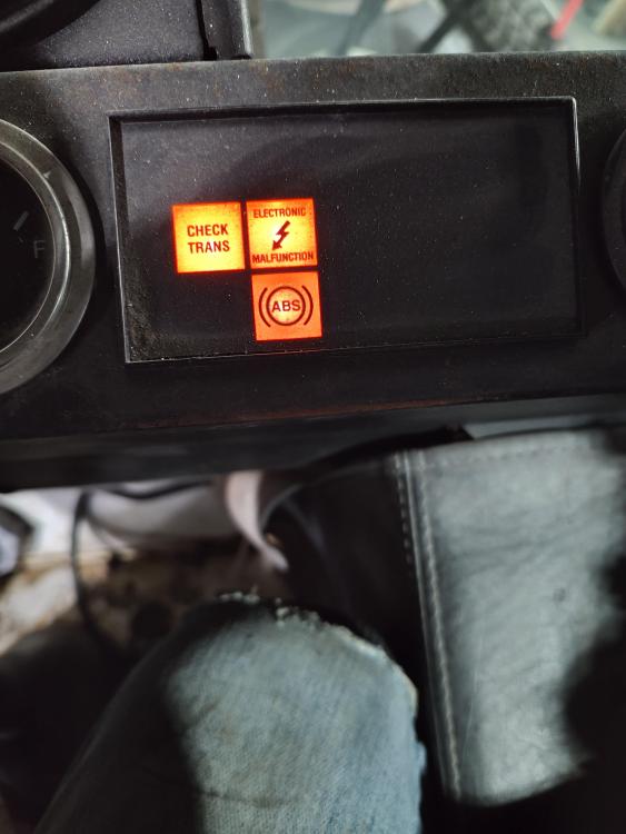

-
MR 688 electrical trouble shooting. No crank
Ryanp replied to Ryanp's topic in Electrical, Electronics and Lighting
joeH, Thanks for all the pictures and insight! I had my mobile mechanic friend come over last night and we determined the ecu was good but that I needed to recheck all my grounds and power connections and clean them up. I will have to get that manual ordered and double check those fuses and relays you pointed out. Also ill look into that trans power. your right I have that harness hanging out in the grille area, thanks for the wire numbers I will have a look to see what I can see. Thanks, Ryan -
MR 688 electrical trouble shooting. No crank
Ryanp replied to Ryanp's topic in Electrical, Electronics and Lighting
Is that book different than what I would have? I see it says 1999 on it. With the AI300 mine is a VMAC4? -
MR 688 electrical trouble shooting. No crank
Ryanp replied to Ryanp's topic in Electrical, Electronics and Lighting
Thanks for the reply. Would you happen to have access to a diagram to show where fuse #71 is? I just went through and tested them all and they test good. Jumped all the open fuse locations and found the flashers but no trans power. Also it will turn over if we power the big relay behind the cab that powers the starter up. I know what you mean about the dirty console. I have a 2001 mr688 that is all oily under there because of oil from the air brake release. Ive cleaned all the trash out but its still dirty and cobbled like no other. thanks, ryan -
MR 688 electrical trouble shooting. No crank
Ryanp replied to Ryanp's topic in Electrical, Electronics and Lighting
Hello I'm working on a 2004 Mack MR688. AI300 with the allison hd4560. Last 6 on the vin, 023615. Sorry for the confusing post. First time and I see that it only works on my desk top. This truck I'm working on was pieced together from 3. Cab, engine/trans, and the original chassis. everything was "VIN matched". So it came as a basket case that was missing some parts but the electrical appeared to be mostly complete. Hard for me to tell whats "extra" because I just need it to run and drive. Its getting a flatbed with water tanks to be a tender truck on our farm. There is still a harness that i believe controlled the front hydraulic pump but its tied in quite a bit to the harnesses that go into the console. Anyway its got a battery in it now and I'm trying to test everything and get it to fire before i go any further with the project. We can jump the relay at the air filter housing and it will engage the starter, slowly but I've only got one battery in it right now. I suspect there are thing unplugged or missing in the console that aren't giving me power where i need it. Currently if i jump in and key it on, 1. "electrical malfunction" light 2.ABS light 3.Hearing some relays in the console clicking like you would expect. 4.The keypad for the trans doesn't light up or do anything. Go to start position on the key, 1.Lights on the dash stay the same and I hear a couple more relays clicking but still no crank. 2.Still no trans power. 3.Not sure if its from the ignition position or the start position but the 4 large relays near the vecu held on by screws get quite warm. Almost hot to the touch. Something is not hooked up or hooked up wrong i assume. I have contacted the dealer who is supposed to send over schematics but haven't seen them yet. Having a hard time knowing what to test for and where, the fuse/relay layout is mostly rubbed of the sticker on the panel and the diagrams I've found are for completely different trucks. If someone has a schematic or some testing ideas I'm all ears. Thanks, Ryan


BMT Forum Logo
