

Fuse Circuit

By Keith S
- 2,664 views
- View Keith S's images
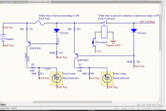
This circuit will be used to show when a fuse is blown or a battery pack contactor (relay) is open. Each of the four packs will have this circuit.
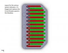
There will be a indicator panel in the glove box (located where the circuit breakers used to be located).
Because this is 200 volts DC, I'm using small neon lamps.
Basically the circuit functions like this (ignore the resistors (R1, R2...) as they simply limit current):
- Pack voltage (200V) flows from the battery and hits the fuse, if the fuse is good the neon lamp circuit is ignored and voltage flows to the Pack Contactor.
- If the Pack Contactor is open (turn off), transistor KSP92BU (in the middle) acts as a switch and turns on the neon lamp
- If the Pack Contactor is closed (turned on), the circuit is ignored and neither neon lamp is on.
- If the fuse is blown, transistor KSP92BU (on the left) acts as a switch and turns on the neon lamp.
- The Pack Contactor neon lamp will be off - which is not really correct because that means the contactor is closed which may not be correct. So I may change the circuit and move the R5 connection to the Battery side of the fuse.
-
 2
2
BMT Forum Logo

Recommended Comments
There are no comments to display.
Join the conversation
You can post now and register later. If you have an account, sign in now to post with your account.