

Vladislav
-
Posts
7,456 -
Joined
-
Last visited
-
Days Won
68
Content Type
Profiles
Forums
Gallery
Events
Blogs
BMT Wiki
Collections
Store
Everything posted by Vladislav
-
I would also think so. Or better to say I just don't see any other reason. Grease overfill is excluded. May be normal in very theory but I wouldn't like such way of things definitely. So seems like setting some reasonable minimum play is the way. Speaking the terminology I also use to have that feeling of getting more and more complicated the more I try to say clearer. I admitted on the forum a few times that American technical terminology is a kind of mess in many cases with plenty of terms of slang origin. I can state this relating to terminology used in Soviet Union design documentation. Although the most Russian technologies of 20th century were based on Western (mostly US and German) designs local engeneers made large job investigating and systemizing the info which followed by designing and establishing strict industrial standards. Those also conteined standartized names for certain parts, units, assemblies etc. Also it was prescribed of what should be called as a part, what is a unit or a assembly etc. Very important point when you read a (good) book of those times and you see a name (a term) used for a certain part that exactly same name would be used all over the book including text in pics, schemas and specifications. Unfortunately modern literature doesn't follow those standards being translated (inprofessionally in many cases) or just written by undereducated specialists.
-
Ok, figured. When you mentioned a "carrier bearing" I got thinking of a bearing in a carrier, a pinion bearing. I always surprized the fact the axle reducer unit is called a carrier (and we even spoke about that on here). The "diff" term also doesn't sound technically correct since there are gears in the carrier also, not a diff only. But the things are as they are. I think determining pre-load in a press or a vise is the right way to go. To my understansding for the particular task you have very light pre-load is needed. Fat or oil used in the original bearing was of much lower standards than modern materials so a bit of pre-load wouldn't make damage. At the same time play may give space for potential vibrations. And I doubt you need extensive pre-load having no plans for really big milage.
-
 If you want accurate figures for your model project don't use sizes measured off a diagram. They're drawn schematically and in the most cases not up to scale. Factory blue print would work but they're for a certain part or a unit, not a whole rig. Another way of scaling off is a photo taken from a big distance. For perfection it's a photo made by yourself using zoom. Sure such approach is seldom achievable so pics from the net makes the job. Look for good ones made at right angle. You need one known measurement (for example the wheel base or a tyre OD) which allows you to count out others by proportioning. You're right The Most of Mack models were offered with different wheel bases. MH was not an exclusion. BTW right at the moment I'm on a hunt for the MH wheelbase chat. Need it for my big scale project. Haven't found any so far but noted a few exact figures. Including that one pointed in the diagram you posted. That figure of 4140 mm means 163 inches. Other figures I previousely saw all were odd numbers (for RW's and CL's too). But for example R-models (along with a few other older ones) are even. This way I suspect odd number for the wheelbase is a feature for MH/RW/CL chassis. If I'm not wrong Mack used to offer a line of wheelbases to choose from with a certain step. Particulary it was 4 or 6 or 8 inches. If I know that step exactly I would be fine with what I'm looking for. Unfortunately IDK yet. Speaking the spring brackets style and other chassis components I have a bunch of pics made from under trucks. I just don't want to flood up the forum with such content which is doubtly interesting for the most of the folks on here. Also they images are heavy and upload capacity of an account is limited (ask me how I know). So PM me your e-mail and I would send what you want to see your way.
 -
Hope for the deal to be done. So what the theory says on the crytical speed? Is it higher for fatter or heavier shaft? Or did just that "seat of pants" engineering work out well enough? And what's up the bearing temp? Do you worry on extra stress put on it by larger shaft? Or did you just serviced it and wanted to check?
-
I made a measurement - the distance between the rails at the very front of MH chassis is 1075 - 1076 mm. Measured over outer sides of the ends of the rails. Answering the other question that MH/RW2 chassis has its unique style and has nothing in common with a Volvo frame.
-
Sounds like the wind blows to the better. I was just going to ask did you have another dry cracked tyre for the swap?
-
Sh*t happens indeed. Sorry to see the tyre didn't hold on enough miles for you. Wonder which size a can of Fix-a-Flat is needed for the case. My guess is 33" OD 12.5" tall or larger.
-
A bit more of useful info
-
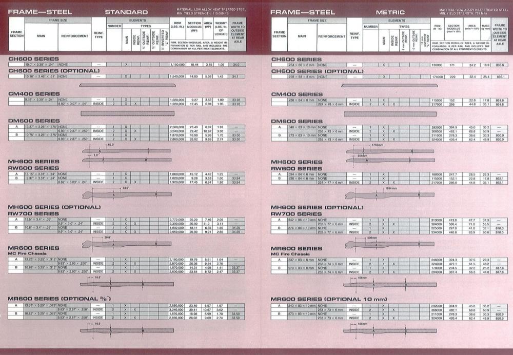
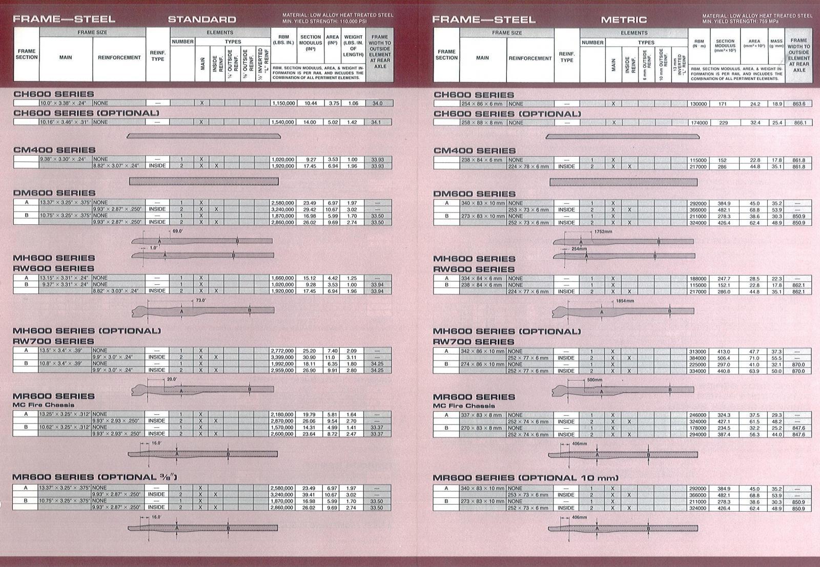
Where are you in the EU? There are a few MH's in The Netherlands and you can usually see them at a Mack day fest. It takes place in authumn though. Or you may travel to my place if such a trip is comfortable for you nowadays MH/RW2/CL chassis is wider at the front. I'm not ready to tell the exact figure, it needs to be measured. Or you can relate it to a truck width by distance between the bumper bolts. You need a good pic of a truck with a bumper removed. Frame rails keep constant distance of 862 mm (measured at the outer sides) over them from the rear end up to nearly the rear point of the tranny. Than further up front they get to the outer sides making the frame wider. Speaking the higth and thickness of the rails there were 2 options. RW600 and standard MH600 had 238-239 mm high boss with 84 mm flanges bent of 6.35 mm (1/4") steel sheet. Factory specs indicate 0.24" (6mm) thickness (meaning it was a metric frame). But actual measurements of my two MH's showed 6.35 not 6.00. One of the trucks was made in (late) 1984 and the 2nd is 1991. The 2nd option was a heavier frame of 274mm high channel with 86 mm flanges 10 mm thick (9.6mm I guess being 3/8") That was a standart chassis for RW700 and optional for MH600. As I understand MH700 has never took place along models offered by Mack. I have many detailed pics of MH/RW chassis. You may PM me for sending some of your way. Recently we discussed that same subject in another thread, you can see a few pics there too Vlad
-
Cool to see! Thanks once more!
-
Ok, the plan got a change. Not to the East coast but Houston TX.
-
Get the tyres off and ship the rest to NJ for the cost of them?
-
They look as an attractive deal indeed. Special thanks for the pics. Just quite long ways from the East coast. Acually I have plenty of troubles to import a truck from the US at the time (mostly due to known circumstances). Might jump into the fire if the stars line up really smooth. But better to avoid new entertainments and concentrate on the projects in progress.
-
Pretty sure that's similar setup to what was used in RD or RW. Watt's had it in the online store, not sure it's still there avalible, needs to check out.
-
Steel dash is welded into the cab structure so you would need a grinder to make that swap. Probably possible if you add a few steel mounting brackets plastic dash is supported with. But on my mind (and many other's on this forum) steel dash is more exotic and rare. So seems more interesting to keep it the way it is. Speaking the cab lengthes early (pre-73-?) cabs were shorter than later ones by 3 inches. Both DM and R. That more relates to the driver place though since DM cab has a kind of a dog house at the right to accomodate the rear portion of the engne. So a co-driver anyway has less leg room in a DM (off-set cab) than in R or RB/RD etc.
-
Yup, as said above! The DM looks very clean. And one interesting A-model concrete mixer. I see it's stored inside. Is that any museum or a private collection? Vlad
-
B-73 Restoration
Vladislav replied to mattb73lt's topic in Antique and Classic Mack Trucks General Discussion
Great news! -
Steering box issue
Vladislav replied to mowerman's topic in Antique and Classic Mack Trucks General Discussion
I haven't put my hands on revising a Mack steering box so far. But pretty sure many guys on here have. Seems worth posting a couple of overall view pics of it and someone may point out further ways to go. -
Ok, the things seem you are closer to the truth than I am (and I expected such the way not opposite). Today I got myself looking for another "threasure in the weeds" which I also removed off a truck a few years back. I made pics but haven't pulled them from my phone. That 2nd unit looked the way you described FW3500 model. Two jaws with no central part at the rod side, two big pins with their ends seen left and right and that threaded rod with nut and washer and rubber bushing. The "recess pattern" style is a little bit different than the 1st unit has but overall looks very close. The one I posted the pic of above has one pin definitely not two and no threaded rod sticking out front. I walked by the place it was laying today to look for the jaw(s). But couldn't see two of them since it was positioned with its face up and I couldn't turn it over alone. All I saw on the diagrams you posted and read in the thread makes me thinking there must be one side jaw. But my memory still whisper of seeing two... So your mentioning of eyes in not the greatest condition may be reffered to more than one person. Once again, many thanks for taking the time and pay attention to my needs. I read that thread about JOT forum (and did that from the moment it was started). Hope the issue will be fixed one day or another. And sure glad to see and communicate with new to this forum truck enthusiasts.
-
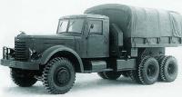
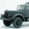
Thanks for sharing these cool pics! Many great looking trucks, a pleasure to see. BTW any info on that dark green H-model? Was it originally imported to Australia or any other story? As I can see on the photo it has its steering wheel on the right side.
-
Thanks for the step by step. The unit looks like FW2000 indeed. But the diagramms show the center plunger and ONE jaw, as you described. And as I remember I saw two side jaws in my wheel. I even started doubting on what I saw. But I belive I checked that out more than 2 or 3 times. Actually I have 3 such identical fifth wheels off 3 trucks. And going to revise at least 2 of them. And (again) as I recall all they had 2 side jaws. Ok, I'm going to put my hands on the 1st one in the nearest days. Just want to wait a dry time, it was raining really hard today.
-
Steering box issue
Vladislav replied to mowerman's topic in Antique and Classic Mack Trucks General Discussion
Bob, is that steering box a PS or just mechanical? Those are two almost different stories. -
B61 starter and polarity
Vladislav replied to skydawg's topic in Antique and Classic Mack Trucks General Discussion
Ok, I have a couple of cents to throw into the ring. No theory (it's a late time at me so I'm not leaned toward thinking much) I have two different starters on two different (old) Macks which did DIFFERENT changing polarity. One was installed on 1944 NM-model with 707 EY gasser. When I purchased the truck one of my guys put a battery on it after which I fired up the engine and drove the truck off a trailer and to my yard. The next day when I started investigating the things myself I found out my helper put the chassis wire to the negative terminal of the battery (he just didn't keep in mind existing of the positive ground system). But the truck could drive as I said and I found no hurt to generator or other electrical components. The 2nd starter is for my NR-model with 519 ED Lanova diesel. It's 24V motor which operates with series-parallel setup. I rebuilt that starter and before putting it onto the engine I got to figuring on which terminal to connect to which polarity. Just tested both ways and found out DIFFERENT direction of rotation. Of what I noted two starters had different design. The diesel one had 4 brushes and both armature and housing magnets were wire coils. The one on the gasser was not investigated by me (since it's on the truck and works) but as I recall at the moment I saw 6 brushes inside it. -
Hope they will work for you. I kept my eye on them for a long while. But my actual need was just the rubber bushings since my metal parts were Ok. And with current headaches to ship to my place I figured I'd live without 'em.
-
Thanks the great Gentlemen! Now I just need a bit of time to read the text in those manuals to be completely prepped for biting the bullet. Illustrations may work faster though. Hope to have the thing apart the other day. Relating to the manuals my wheel looks as a kind of FW2000 but with two jaws and "C-pinion" at the cab side. Probably some modification or maybe a differently named model. But I hope general design is the same for many models. There may be an issue identifying replacement parts though but I use to double check suiteness by fitting sizes etc. I will post the results as soon as I have all the pieces blown separately. Even if I get being one legged by the plate fallen onto my foot


BMT Forum Logo
