Pawel Posted April 10, 2014 Share Posted April 10, 2014 Hello!As many of you know, I'm working on a model of a 1:24 RW Superliner. I'm about to put the cab on the frame. There's a lot of plumbing on the firewall and I'd like to show some of that in my model. Could you help me please? I I would need a photo of that firewall and some explanation where all the valves are and where the brake lines go. Any other comments on other system are of course also welcome. Unfortunately I live very, very far away from the nearest R model around Thanks a lot in advance and have a nice dayPaweł Quote Link to comment Share on other sites More sharing options...
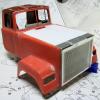
Pawel Posted April 11, 2014 Author Share Posted April 11, 2014 OK, let me get more specific: Let's take this picture (Thanks again Vlad!):1) What valves hide under there? I believe that's a major brake system node2) Is it also a brake system component? What is it?3) How about this? Do any/Which of those hoses go to the dash mounted valves?4) Non brake related: What can you tell me about this wiring detail?Thanks a lot in advance, any info would be a great help. additional photos heartly welcome! Have a nice dayPaweł Quote Link to comment Share on other sites More sharing options...
Vladislav Posted April 11, 2014 Share Posted April 11, 2014 Hi Pawel!I'm not ready to provide complete help to you this time but I try a little.Little note - R-model brake system components and RW ones you're looking over are located slightly different.So you better determine your request for RW.1. The point you marked - there's no air valve but just pipes and harnesses.The valve you mean is a threadle or foot brake valve.It's located just underneath of a brake pedal so its flage lays on and is fitted to a cab's floor.So a brake pedal fits to its top and its most body with pipes connected is under a cab.You can see it on that pic but to the right and lower from the "1" point, the horizont pipes come from it.You can find that valve on the different shots I sent to you when look carefully under the cab floor.I think it's the same for R and RW. You can also see it on the Watts R-model shop in the "brake parts".2. - not ready to tell, looks like a pressure governor but I'm not shure.3. - more looks like the heater valve on the cooling sys.pipes, you need to follow those pipes to figure out.4. - the wire connector to match cab and chassis harnesses.Better wait for more advices because I might be some wrong.Here are the pics of the threadle valve of that red RW from the side and the shot of the valve on my MH.The last one is different, longer body with different connecting points, but it may help in general.Vlad Quote Никогда не бывает слишком много грузовиков! leversole 11.2012 Link to comment Share on other sites More sharing options...
turckster Posted April 13, 2014 Share Posted April 13, 2014 Numbers 1&2 look like the foot and check valves (treadle valve)#3 looks like an air operated windshield wiper motor#4 is the cab to chassis wiring block. Most major chassis to cab components are connected here. Quote Link to comment Share on other sites More sharing options...
Pawel Posted April 14, 2014 Author Share Posted April 14, 2014 Vlad - thanks again for your help and for the photos. The first one you posted - I already looked at it, but couldn't quite figure it out. The second one helps a lot.turckster - thanks a lot!Can anyone tell me the exact designation on the threadle and check valves on the Superliner? Or maybe someone could post some more photos here? Thanks in advance and have a nice dayPaweł Quote Link to comment Share on other sites More sharing options...
Pawel Posted April 16, 2014 Author Share Posted April 16, 2014 OK - can somebody tell me, what that thick pipe is, running parallel and under the "3" arrow, parallel to the steering shaft? It shows white on the photo I posted. I'm guessing it's the speedometer drive shaft - is that right? Where does it go on the other end?Thanks in advance and have a nice dayPaweł Quote Link to comment Share on other sites More sharing options...
85snowdog Posted April 16, 2014 Share Posted April 16, 2014 OK - can somebody tell me, what that thick pipe is, running parallel and under the "3" arrow, parallel to the steering shaft? It shows white on the photo I posted. I'm guessing it's the speedometer drive shaft - is that right? Where does it go on the other end?Thanks in advance and have a nice dayPawełPawel, the item you are asking about is not the speedo, it is the clutch cable, it goes to the clutch linkage on the left side of the bell housing. Hope this helps.Keith Quote Keith Link to comment Share on other sites More sharing options...
Pawel Posted April 16, 2014 Author Share Posted April 16, 2014 Hello Keith!Thanks a lot, very good info. Do you happen to have any pics of this area?Thanks again and have a nice dayPaweł Quote Link to comment Share on other sites More sharing options...
85snowdog Posted April 17, 2014 Share Posted April 17, 2014 Pawel , I took a pic for you. You should make sure this will be accurate for your model. The pic is from a 1986 RD688 with an E6 350 hooked to an 8LL transmission.My impression is you are making an RW model. I think (but not sure) the importance iswhat motor and trans is in it. If it has an E9 with a 12 speed say, I don't think it will be the same. But I honestly have no idea.Maybe someone that knows more can help you. I don't want to steer you wrong. Its probably the small details that make the model.The Pic is from the ground behind the fuel tank, looking forward.Keith Quote Keith Link to comment Share on other sites More sharing options...
Pawel Posted April 17, 2014 Author Share Posted April 17, 2014 Keith - thanks a lot for the picture! It's really valuable to me - you don't find a photo of a detail like that on the internet! You're right, I'm going for the detail. My model has a Cummins Big Cam II and a Fuller Roadranger tranny. I have to look at the clutch some more.So thanks again and have a nice dayPaweł Quote Link to comment Share on other sites More sharing options...
Vladislav Posted April 24, 2014 Share Posted April 24, 2014 Update on a threadle valve.Here you can see it on my R-model, I was going to provide revision of it and looked over with the camera (first 2 pics.)Than there's the pic from Watts web site (there's the better one there). This one is slightly different, has lower part of the less size then the upper one.The valves on my R's and MH (the last two shots-MH) are almost the same with exception of difference in upper section wich fits to the cab's floor by different way in a conventional and cabover, and the pipe ports.The ports: both valves have them 8, of 2 on 4 sides. My R has 8 pipes attached to. The MH has 6 pipes (of 2 on 3 sides) and just two plugged up ones on the 4th side. A R-moder and a RW has pedal with a pedestal mounted on a floor with a valve body under it. MH has additional section to fit to the floor from underneath. As for the pipes... You should carefully look over the red truck pics trying to figure out their ways. Step by step. Any pipe diargamm might help. I have it not, sorry. Quote Никогда не бывает слишком много грузовиков! leversole 11.2012 Link to comment Share on other sites More sharing options...
Pawel Posted April 24, 2014 Author Share Posted April 24, 2014 Hello Vlad!Very good info here - thanks a lot! I already tried to build a valve like that, but now that I have new info, I think I'm going to refine it.Could anybody please help me with which line goes where? I'm especially interested in the lines that go into the cab.Thanks a lot in advance and have a nice dayPaweł Quote Link to comment Share on other sites More sharing options...
gearhead204 Posted April 24, 2014 Share Posted April 24, 2014 Pawel: I think a air line schematic of a superliner would be easer to use for accurate placement of the lines. Then use our photos to get realistic routing and placement of the lines. Hopefully a member has a schematic for a R model they will post. Quote Link to comment Share on other sites More sharing options...
Pawel Posted April 24, 2014 Author Share Posted April 24, 2014 Hello!Agreed - just getting an air brake schematic for a tractor isn't so easy If somebody has such a schematic please post it here!Thanks in advance, have a nice dayPaweł Quote Link to comment Share on other sites More sharing options...


Recommended Posts
Join the conversation
You can post now and register later. If you have an account, sign in now to post with your account.